A method and apparatus for controlling a jet loom

A technology of jet loom and control unit, applied in looms, textiles, papermaking, textiles, etc., to improve weaving quality and reduce fluid consumption

Active Publication Date: 2013-08-21
USTER TECHNOLOGIES +1
View PDF17 Cites 3 Cited by
  • Summary
  • Abstract
  • Description
  • Claims
  • Application Information

AI Technical Summary

Problems solved by technology

As a reaction to the detection signal, a temporary change in the supply pressure of the blowing nozzle is caused

Method used


Image

  • A method and apparatus for controlling a jet loom
  • A method and apparatus for controlling a jet loom
  • A method and apparatus for controlling a jet loom

Examples


Embodiment Construction

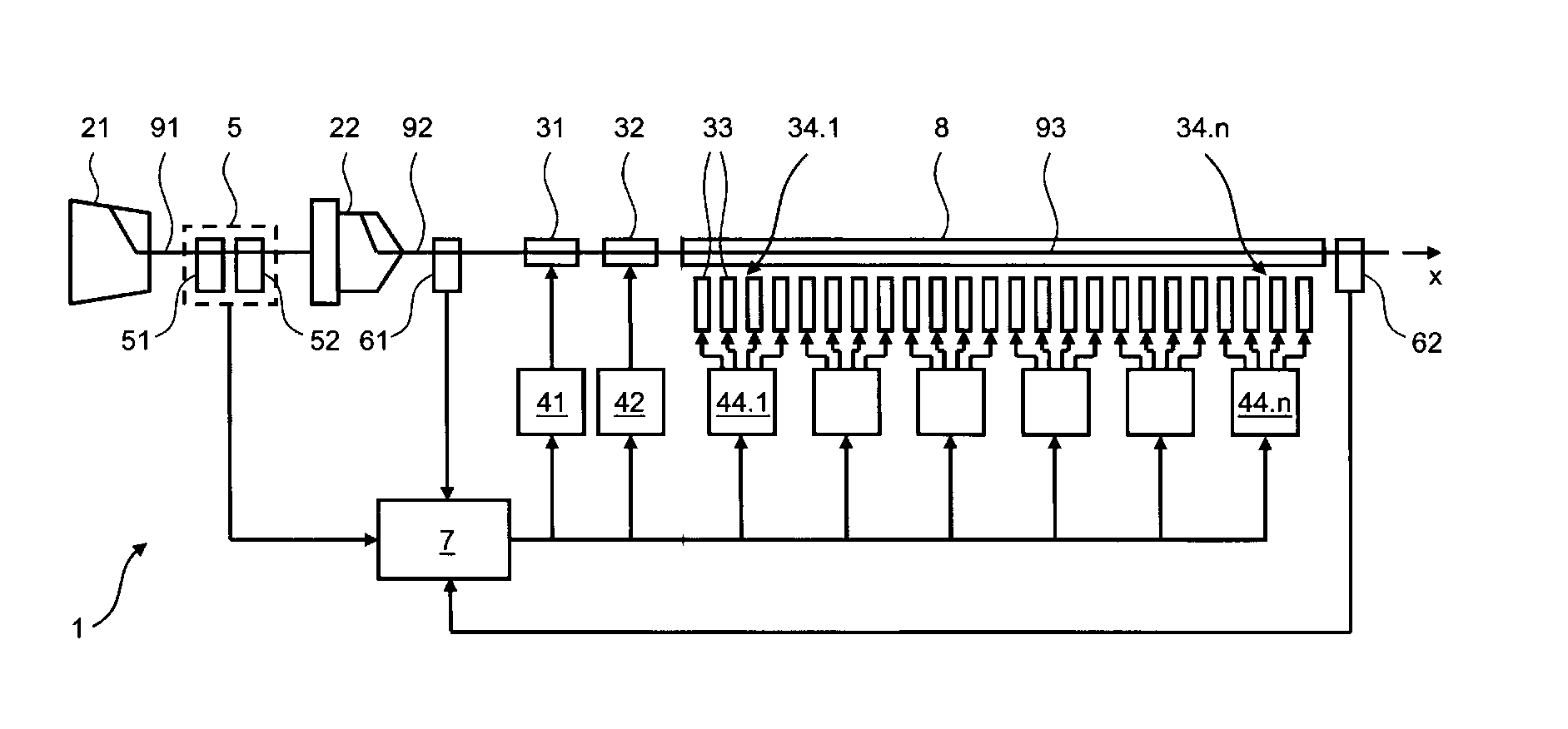
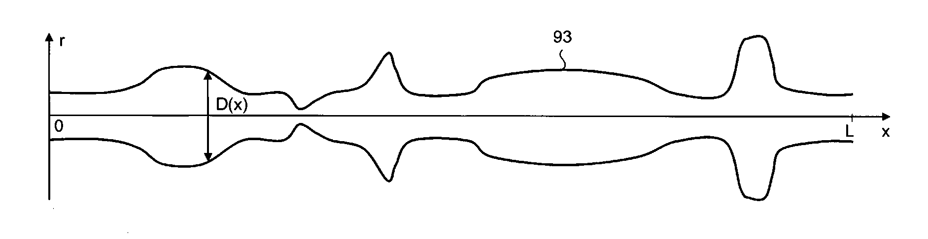
[0035] figure 1An air-jet loom jet loom 1 with a control device according to the invention is shown schematically. In this embodiment, the air-jet loom The jet loom 1 is designed as an air-jet loom. A yarn 91 designated as a weft yarn is provided on the bobbin 21 . The yarn 91 is transported from the bobbin 21 to the weft yarn storage unit 22, which may be designed as a drum-type storage unit. The weft yarn 92 extracted from the weft yarn storage unit 22 is accelerated by one or more accelerating nozzles 31, 32 (also referred to as main nozzles) and supplied to the air supply pipe 8, which is arranged in a shed forming device (not shown) formed in the shed. A specific weft yarn segment 93 inserted into the air supply tube 8 along its longitudinal direction x is called a pick 93 . The pick yarn 93 is conveyed through the air supply pipe 8 by a plurality of auxiliary nozzles 33 . The auxiliary nozzles 33 are preferably divided into a plurality of nozzle groups 34.1, . . . ,...


PUM


Abstract

A method for controlling a jet loom (1) is proposed. The jet loom (1) contains a plurality of relay nozzles (33) arranged along a fluid feed conduit (8). A weft yarn (93) is introduced into the fluid feed conduit (8), the relay nozzles (33) are actuated so as to eject time- staggered fluid pulses which produce a fluid flow in the fluid feed conduit (8), and the weft yarn (93) is conveyed by the fluid flow through the fluid feed conduit (8). The relay nozzles (33) are actuated based on a local distribution of characteristics within the respectively conveyed weft yarn section (93). Thus, the energy and air consumption of the jet loom (1) are reduced and the productivity of the jet loom (1) is increased

Description

technical field [0001] The invention according to the preambles of the independent claims relates to a method and a device for controlling a jet loom. Background of the invention [0002] So-called yarn clearers are used in spinning machines or bobbin winding machines to ensure yarn quality. Such a device is known, for example, from EP-0'439'767A2. It includes a measuring head with at least one sensor that scans the moving yarn. Commonly used sensor principles are capacitive (see eg EP-0'924'513A1) or optical (see eg WO-93 / 13407A1). [0003] It has been proposed to scan the yarn with different sensors and to combine the different sensor signals for evaluation. For example US-6,798,506 B2 teaches to arrange two sensors, one behind the other along the yarn path. The first sensor measures the optical reflection from the yarn; the second sensor measures the mass or diameter of the yarn capacitively or optically, respectively. The output signals of the two sensors are evalua...

Claims


Application Information

Patent Timeline
Patent Type & Authority Applications(China)
IPC IPC(8): D03D47/30D03D47/34D03D47/36
CPCD03D47/304D03D47/36
Inventor M·J·阿尔布雷克特卡斯滕·米德P·皮拉尼拉法里奥·斯托兹铃木透稻村贵裕奥田泰治郎
Owner USTER TECHNOLOGIES
Why Eureka
Try Eureka