Automatic purging system in water-ballast condenser line pipes

An automatic cleaning and condenser technology, applied in the field of cleaning systems, can solve the problems of wasting water resources, increasing the amount of returned balls, and expensive use costs, so as to ensure the cleaning effect, prevent a large amount of loss, and reduce manufacturing costs and use costs Effect

Active Publication Date: 2004-11-17
陈舜周
View PDF1 Cites 11 Cited by
  • Summary
  • Abstract
  • Description
  • Claims
  • Application Information

AI Technical Summary

Problems solved by technology

[0003] This type of cleaning system, because the final channel is connected to the air, directly discharges the cooling circulating water into the sewer outside the system, resulting in a large loss of cooling circulating water, a serious waste of water resources and secondary pollution; in addition, the The ball returning power of the system comes from the pressure difference water flow generated by the continuous discharge of cooling water in the final channel to drive the balls to flow from the separator to the recirculation system. However, once the pressure difference is insufficient, the balls will not return to the recirculation system immediately. In the process, the balls are backlogged in the separator, resulting in: 1. Insufficient return of balls, which directly affects the cleaning effect each time; 2. Due to the structural defects of the separator system and the backlog of small balls, the resistance of the separator system increases , the pressure difference is reduced, which not only increases the lack of returning balls, but also seriously affects the flow rate, flow rate and pressure loss of the cooling cycle system, resulting in a decrease in heat exchange rate; 3. Many condenser pipes have not been cleaned, and it takes a long time Scaling and blockage of the condensing pipe will appear, which will cause serious consequences.
[0004] In addition, the position of the second channel of the system is set on the opposite side to the first channel, resulting in pressure loss, poor water flow, and insufficient impetus for injecting the balls into the cooling pipeline, which cannot ensure that the balls in the upper chamber are in the same position. All the cooling water pipes are injected in a short period of time, which affects the comprehensive cleaning effect each time
Furthermore, one system of this system can only clean one condenser, and the cleaning of multiple condensers requires multiple cleaning systems, which are extremely expensive to use.

Method used


Image

  • Automatic purging system in water-ballast condenser line pipes
  • Automatic purging system in water-ballast condenser line pipes
  • Automatic purging system in water-ballast condenser line pipes

Examples


Embodiment Construction

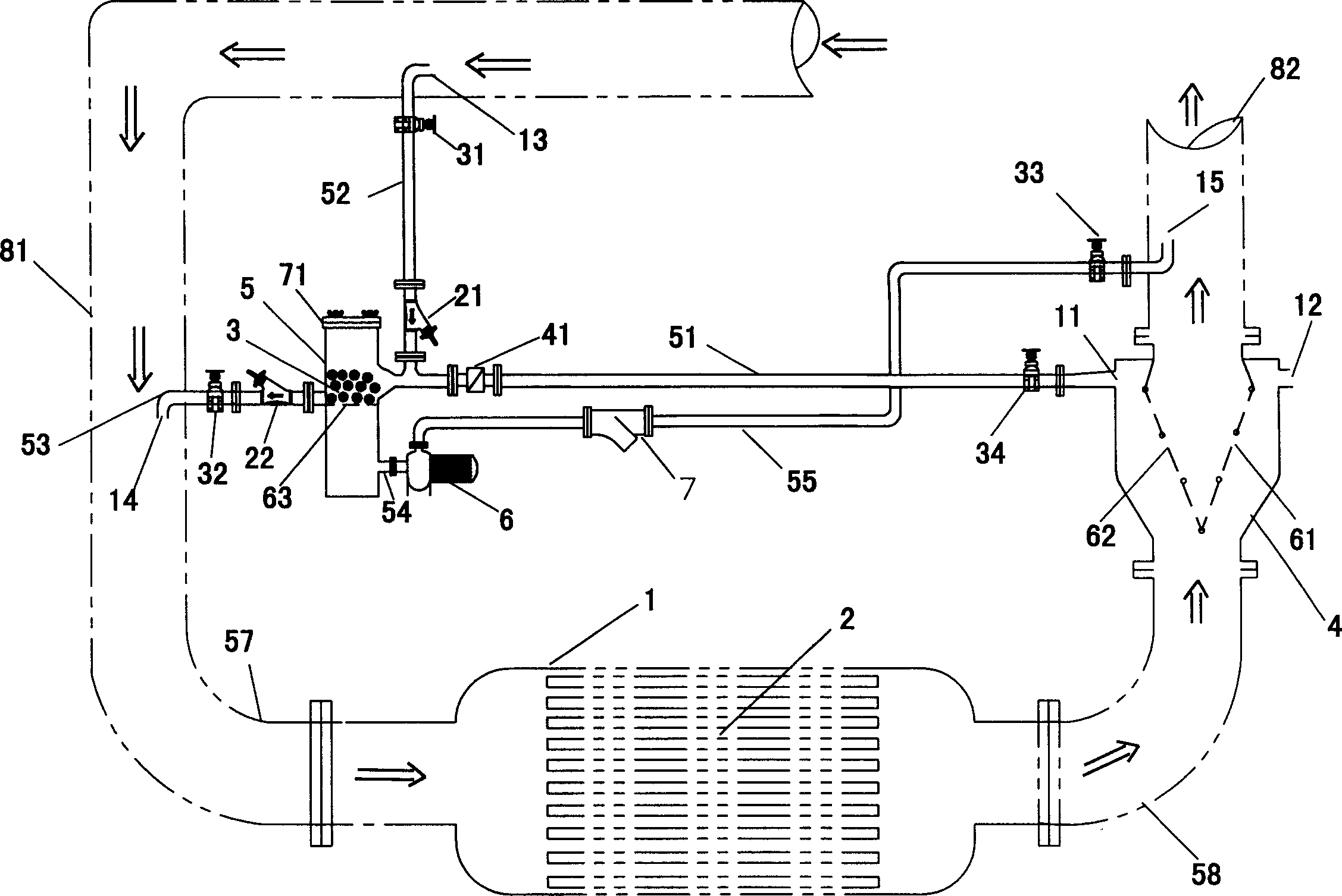
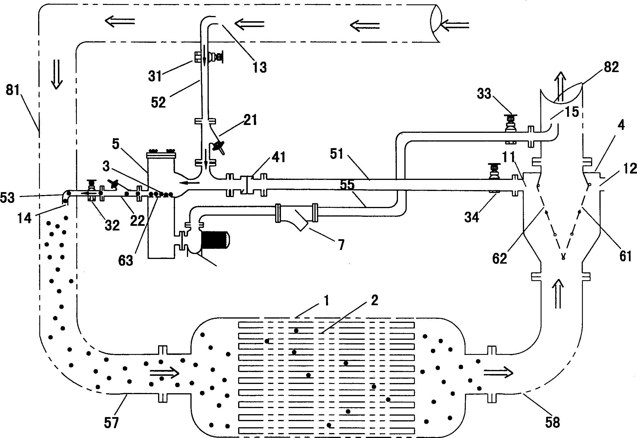
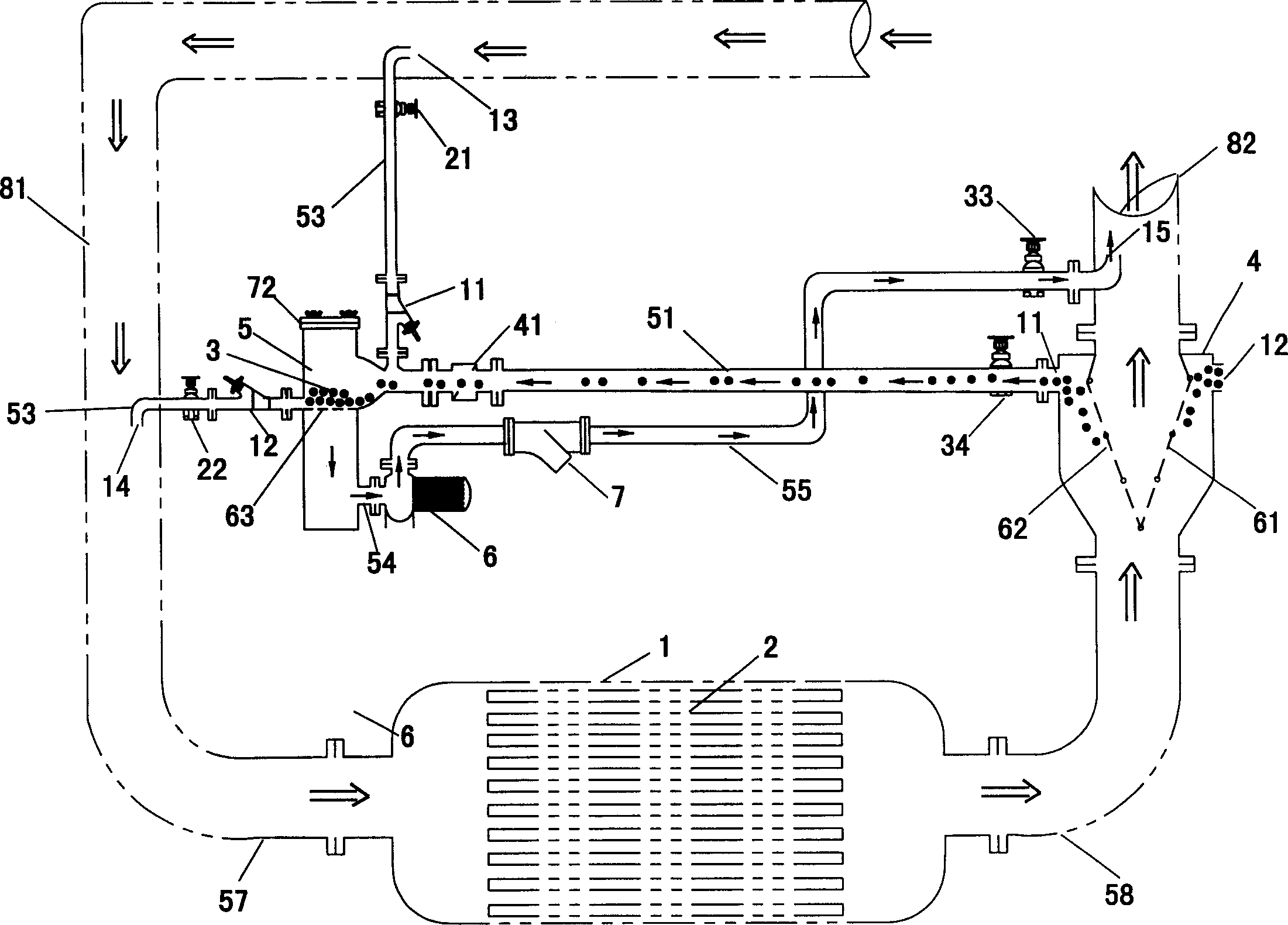
[0018] figure 1 The cleaning system shown comprises a condenser 1 comprising a conduit 2 in the form of a plurality of parallel spaced tubes through which a cooling fluid such as water circulates from a cooling water inlet 57 To the cooling water outlet pipe 58.

[0019] The cooling fluid comprises a number of cleaning pellets 3 forced to flow with the cooling fluid through the condensing tube 2 to prevent particle accumulation or deposits in the condenser tubes which tend to block or corrode the tubes. The balls 3 are made of a spongy material with a diameter slightly larger than that of the condenser tubes, so that they rub against the inner walls of the tubes, thereby keeping them clean. The technique of cleaning the tubes of condensers and other forms of heat exchangers with cleaning pellets is well known.

[0020] The ball returning controller 4 is arranged between the cooling water outlet pipe 58 and the downstream side 82 of the cooling water pipeline. like Figure ...


PUM


Abstract

The invention is a kind of automatic rinsing system for water carrying condensator channel, which includes a small ball flows from upstream to downstream with water, ball-back controller for taking out the ball from water at the downstream, and ball recirculating device for carrying the ball to upstream, the character lies in: the lowest pressure source of the recirculating device is connected to a pump, there sets a filter on the channel connected to the water outlet, which is connected with the downstream side of cooling pipe. The ball-back controller includes two pieces of comb structure filter meshes which made up an isosceles triangle, separates the ball-back controller into two layers; the upper layer forms tow ball-back rooms. The cross-section of the ball-back controller is bigger than cooling channels', the main shell of the ball-back controller is rectangular, three surfaces of which set windows. The system has an excellent effect, the water can be circulated.

Description

technical field [0001] The invention relates to a cleaning system for cleaning a condenser in a central air conditioner, especially for cleaning pipes of a heat exchanger used in the condenser. Background technique [0002] The present invention is particularly directed to the cleaning system described in Chinese invention patent 96107005.6. Such a cleaning system includes pellets that circulate with the water flow through the pipe from its upstream side to its downstream side, a separator system for separating the pellets from the water stream at the downstream side of the pipe, and a system for recirculating the pellets. Back to the recirculation system on the upstream side of the pipeline. In Chinese invention patent 96107005.6, the final channel of the recirculation system is connected to the atmosphere; the separator system includes a grid connected to the ball catcher housing on the downstream side of the pipeline, the grid is located in the ball catcher housing, form...

Claims


Application Information

Patent Timeline
Patent Type & Authority Applications(China)
IPC IPC(8): B08B9/04F28G1/12
Inventor 陈舜周
Owner 陈舜周
Why Eureka
Try Eureka