Image projection or display system

An image and projection technology, used in image communication, light guides of lighting systems, components of TV systems, etc., can solve problems such as damage to the performance of polarizers

Inactive Publication Date: 2004-11-17
INTERDIGITAL CE PATENT HLDG
View PDF0 Cites 2 Cited by
  • Summary
  • Abstract
  • Description
  • Claims
  • Application Information

AI Technical Summary

Problems solved by technology

In addition, the absorbed light is converted to heat which can damage the performance of the polarizer

Method used


Image

  • Image projection or display system
  • Image projection or display system
  • Image projection or display system

Examples


Embodiment Construction

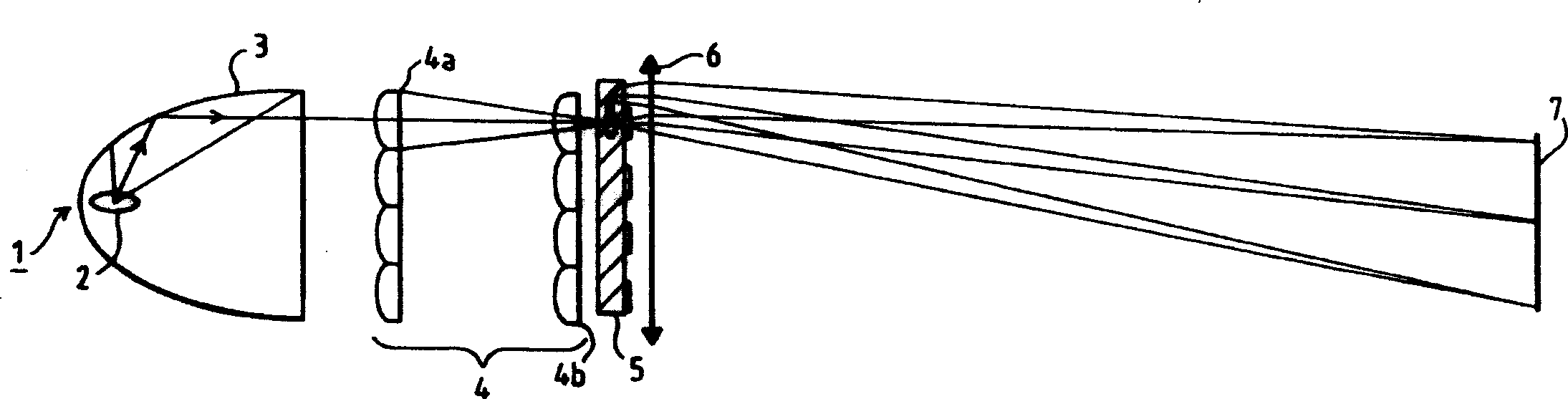
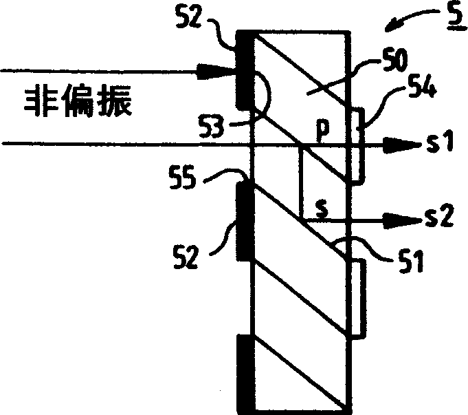
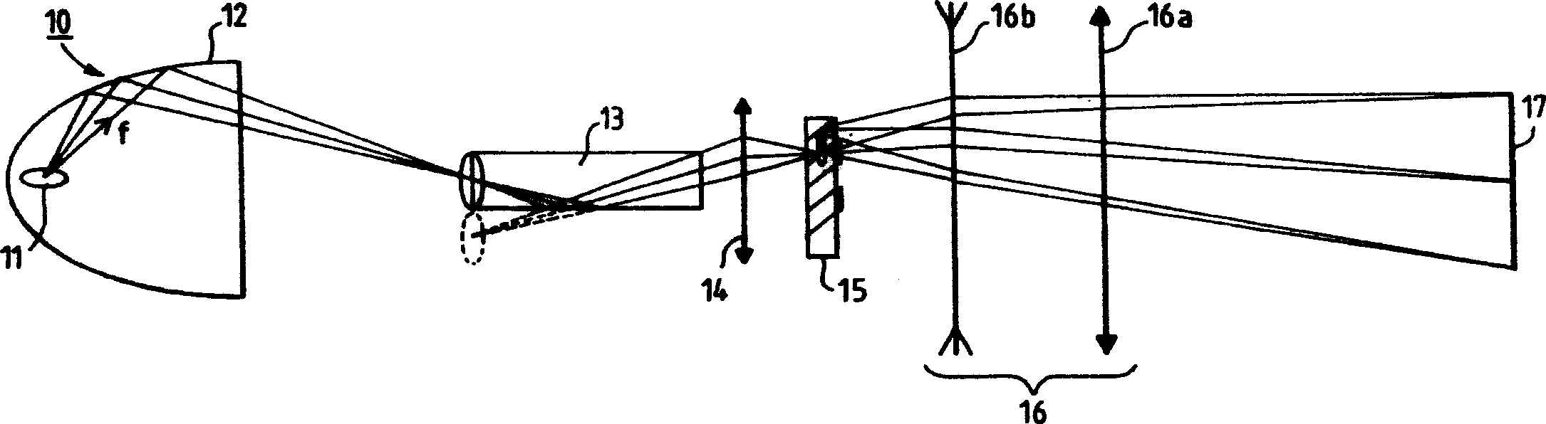
[0033] First, refer to Figure 3A with 3BAn embodiment of the projection system according to the present invention is described. Illustratively, the system according to the present invention has an illumination device 10 consisting of a light source 11 and a reflector 12 for directing a light beam on an imager 17. According to the present invention, the optical integrator system composed of the integrator light guide 13 is arranged after the reflector 12. At the output of the light guide, a first lens 14 is provided, and then a polarization beam splitter or PBS 15, a second lens group 16, and an imager 17 are provided. The various elements of the system will now be described in more detail. In the illustrated embodiment, the light source 11 is composed of a discharge lamp, i.e., a xenon or MHL type arc lamp. The light beam from the light source 11 is directed to the imager 17 by the reflector 12. The reflector 12 may be a parabolic reflector associated with a condensing lens that ...


PUM


Abstract

The invention concerns a system for projecting or displaying images comprising an imaging device (17) and means for illuminating the imaging device comprising a light source (11), means (12) for reflecting the light beam derived from the source towards the imaging device and an integrator (13, 20, 21), consisting of a light pipe followed by means to reflect towards the imaging device virtual illumination sources when the light beam is reflected inside the light pipe with, following the means (14) for reflecting towards the imaging device virtual illumination sources, polarisation splitting means (15), the means reflecting the virtual illumination sources imaging said virtual sources on the polarisation splitting means (15). The invention is in particular applicable to LCD imaging devices.

Description

Technical field [0001] The present invention relates to a system for projecting or visualizing images, and more specifically, to a system of this type including an illuminating device with an optical integrator. Background technique [0002] In order to project or visualize an image, it is known to use, for example, an imager composed of optical valves such as a transmissive or reflective liquid crystal system, in which the transparency of each image-formatter element is controlled It is a function of the brightness of each point of the image to be formed. [0003] In the case of projection, the light energy is provided by a lighting device, which most often consists of a lamp and a reflector, which is used to direct the light beam to the light valve. [0004] Because there is a lot of light loss in the system, the illumination of the imager needs to be uniform and a higher light flux is used to perform the illumination of the imager, so that the projected or visualized image cor...

Claims


Application Information

Patent Timeline
Patent Type & Authority Applications(China)
IPC IPC(8): G02B27/00G02B27/28G02F1/13357G03B21/00G03B21/14H04N5/74
CPCG02F2001/13355G02B27/0994G02B27/286G02B27/0927G02B27/285H04N5/7441G02F1/13362G02F1/13355
Inventor 瓦尔特·德拉日奇德尼·巴塔雷尔
Owner INTERDIGITAL CE PATENT HLDG
Why Eureka
Try Eureka