Lighting device for testing substrate

A technology for lighting devices and substrates, which is applied to measurement devices, instruments, radiation pyrometry, etc., can solve the problems of poor accuracy, long inspection time, and inconvenient inspection.

Inactive Publication Date: 2004-11-24
DE&T
View PDF1 Cites 9 Cited by
  • Summary
  • Abstract
  • Description
  • Claims
  • Application Information

AI Technical Summary

Problems solved by technology

[0016] First, referring to FIGS. 3A and 3B , the method for inspecting a large-sized substrate by moving the lighting device in left/right or up/down directions is inconvenient for inspection when moving the lighting device to multiple parts of the substrate. , because the illumination device can only illuminate a limited portion of the substrate
Since the entire substrate is not inspected at the same time, but is inspected piece by piece according to the area that can be illuminated by the lighting device, it takes a long time to inspect the entire large-sized substrate, and the accuracy is

Method used


Image

  • Lighting device for testing substrate
  • Lighting device for testing substrate
  • Lighting device for testing substrate

Examples


Embodiment Construction

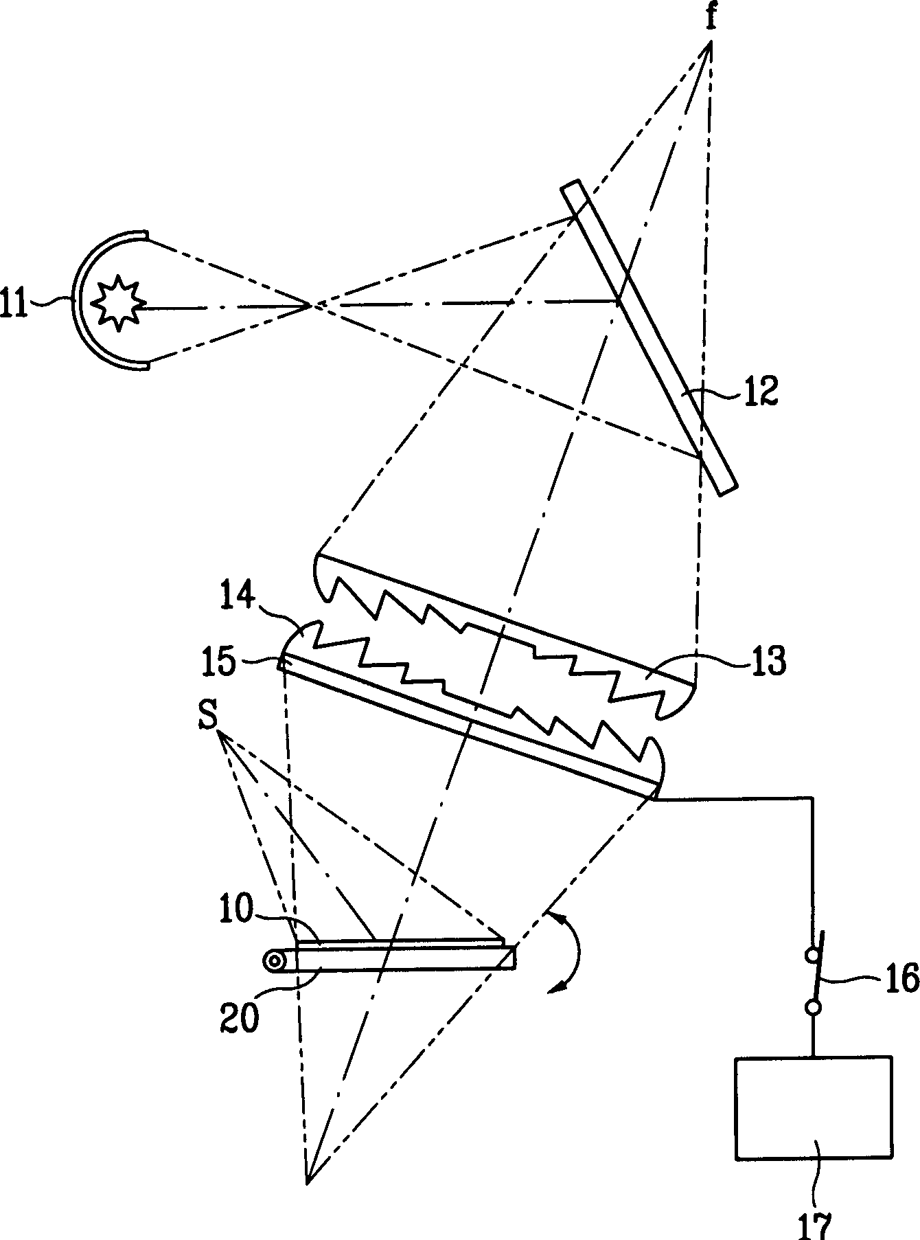
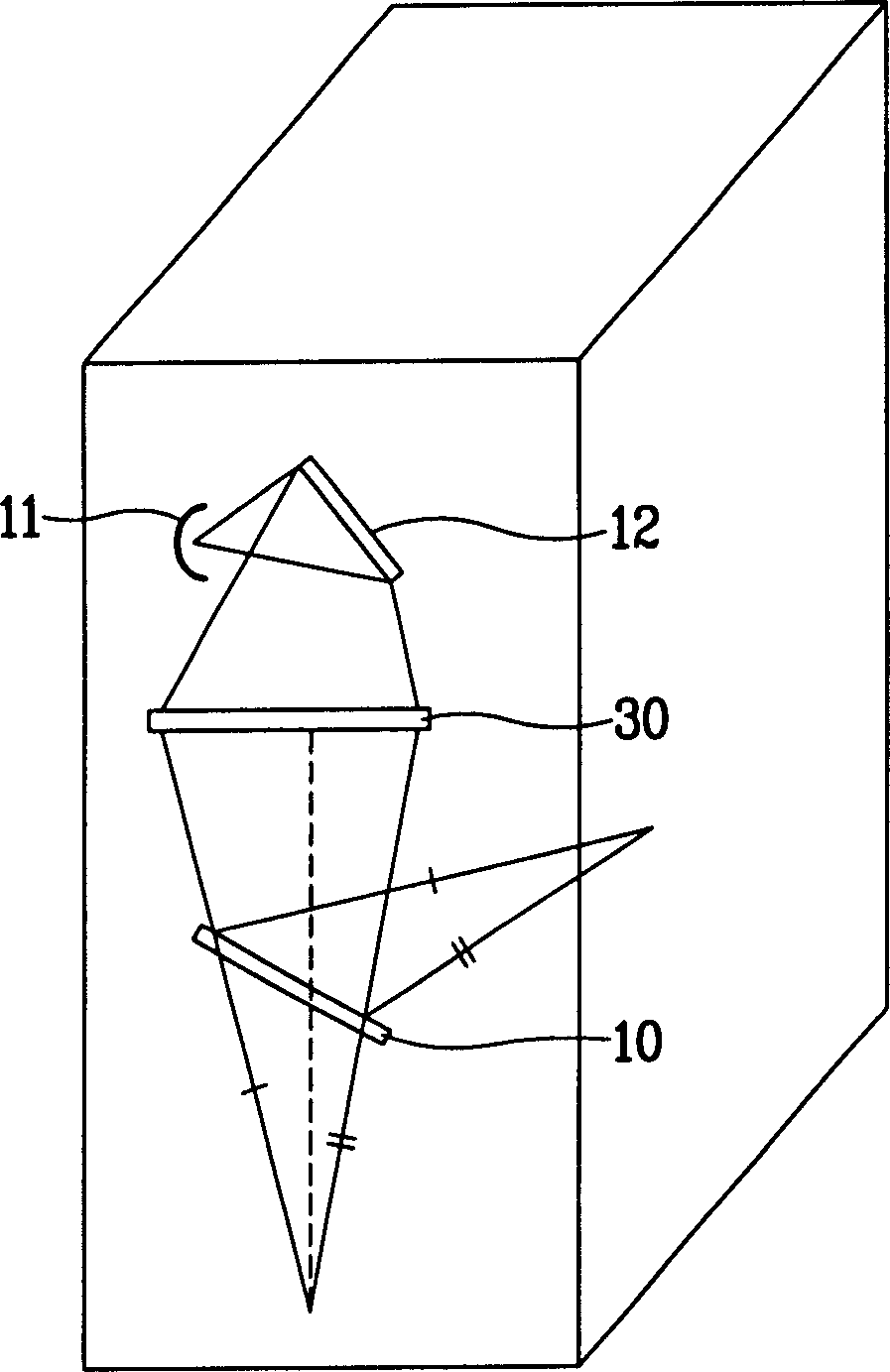
[0042] DETAILED DESCRIPTION OF THE PREFERRED EMBODIMENTS The present invention will now be described in detail with reference to preferred embodiments of the present invention and with reference to the accompanying drawings. attached Figure 5A and 5B The shown embodiment illustrates an illumination device for inspecting a substrate according to a first embodiment of the present invention when only one illumination device is used.

[0043] see Figure 5A , the illuminating device for inspecting substrates comprises: a mirror 120, which is used to reflect light from a light source 110, which moves in an up / down or left / right direction on a curved surface; and a Fresnel lens 200, the Fresnel lens is used to focus the diverging light from the mirror 120 to a focal point 'P' and illuminate the substrate 300 on the stage.

[0044] In this case, see Figure 5B , the divergent light reflected by the mirror 120 is focused by the Fresnel lens 200 and irradiated to the substrate 300...


PUM


Abstract

A lighting apparatus is provided to simplify the movement structure of the lighting apparatus by lighting the wide area of a substrate through the use of plural lightings. A lighting apparatus comprises a plurality of mirrors(130,140) for reflecting the light beams generated from a plurality of light sources(110,120); and first and second Fresnel lens(200,210) for focusing the diffused light beams reflected from each of the mirrors to a single focusing point, and radiating the focused light beams to a substrate(100) mounted on a stage. The light beams radiated to the substrate from the first Fresnel lens and the second Fresnel lens are partially overlapped.

Description

technical field [0001] The present invention relates to an illumination device for directing light onto a large substrate for visual inspection of defects. Background technique [0002] Usually, a visual inspection, that is, an inspection with the naked eye, is carried out in order to find out that the substrates of semiconductor wafers or LCD (Liquid Crystal Display), PDP (Plasma Display), or EL (Electroluminescent) substrates are left during the production process. defects, such as foreign matter or spots. In this case, in order to easily find defects, the entire substrate is uniformly illuminated with one illuminating device, and spots and defects on the substrate can be easily found by utilizing the light reflected on the substrate. [0003] A light-focusing illumination device using a Fresnel lens in the prior art transmits light from a light source through the Fresnel lens and directs (irradiates) the light onto a substrate so as to uniformly illuminate the substrate....

Claims


Application Information

Patent Timeline
IPC IPC(8): G01J3/10G01N21/27G01N21/57G01N21/88
Inventor 南宫墣朴昌铉裵基先沈在信金炫秀
Owner DE&T
Why Eureka
Try Eureka