Control circuit for electric refrigerator

A technology for controlling circuits and refrigerators, which is applied in the direction of using electric methods for temperature control, reactive power compensation, reactive power adjustment/elimination/compensation, etc., and can solve the problem of not being able to further and more effectively improve power usage efficiency, defrosting timers, etc. The electricity use efficiency has not been improved and other problems, to achieve the effect of improving the electricity use efficiency, prolonging the life, and improving the efficiency

Inactive Publication Date: 2004-11-24
LG ELECTRONICS (TIANJIN) APPLIANCES CO LTD
View PDF0 Cites 0 Cited by
  • Summary
  • Abstract
  • Description
  • Claims
  • Application Information

AI Technical Summary

Problems solved by technology

[0010] However, in the control circuit of the above-mentioned prior art refrigerator, only the power usage efficiency of the compressor is improved, but the power usage efficiency of other l

Method used


Image

  • Control circuit for electric refrigerator
  • Control circuit for electric refrigerator
  • Control circuit for electric refrigerator

Examples


Embodiment Construction

[0024] The control circuit of the refrigerator of the present invention will be described in detail below with reference to the accompanying drawings.

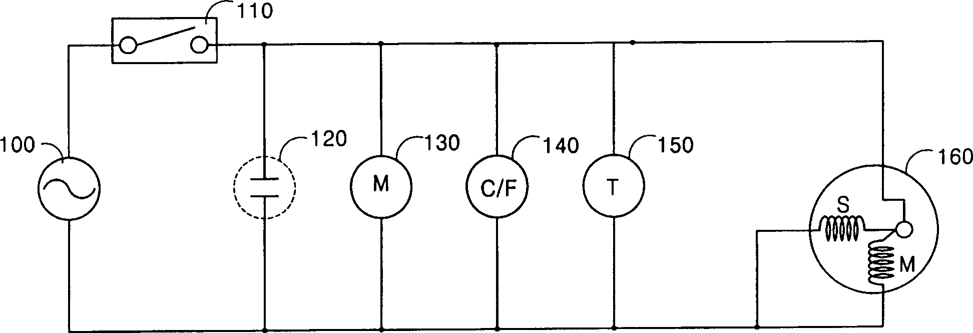
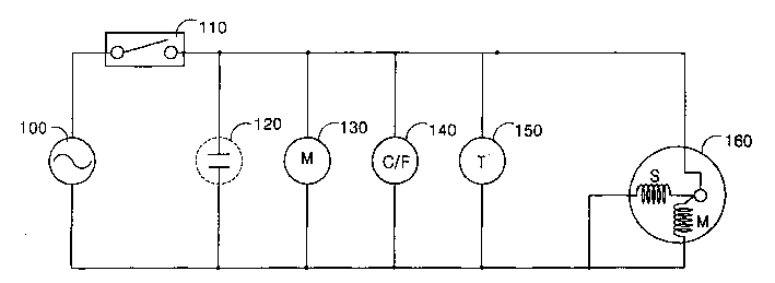
[0025] figure 2 The control circuit diagram of the refrigerator of the present invention is shown.

[0026] As shown in the figure, the control circuit of the refrigerator of the present invention generally includes a power terminal 100 , an automatic temperature regulator 110 , a compressor 160 , a fan motor 130 , a cooling fan motor 140 , a defrosting timer 150 and a capacitor 120 . The above-mentioned power terminal 100 is used to apply power to the product; the above-mentioned automatic temperature regulator 110 is used to control the application of power according to the temperature in the box; the above-mentioned compressor 160 is used to compress the medium; the above-mentioned fan motor 130 is used to drive the fan; the above-mentioned refrigeration fan motor 140 is used to drive the cooling fan; the defrost timer 15...


PUM


Abstract

The present invention relates to refrigerator, and is especially refrigerator control circuit capable of improving load power utilizing efficiency. The refrigerator includes compressor for compressing medium to regulate temperature inside the refrigerator, refrigerating fan to exhaust cold air into refrigerator, defrosting counter to count defrosting time, fan motor and other load. The control circuit for the refrigerator includes automatic temperature regulator connected to power source to regulate temperature inside the refrigerator automatically and capacitor connected parallelly to the automatic temperature regulator to improve the electric power utilizing efficiency of load. The present invention raises the efficiency of refrigerator, prolongs the service life of capacitor and lowers cost.

Description

technical field [0001] The present invention relates to a refrigerator, and furthermore, relates to a control circuit (A control circuit of refrigerator) capable of improving the electricity usage efficiency of the load of the refrigerator. Background technique [0002] Referring to the accompanying drawings, the control circuit of the prior art refrigerator is described as follows. [0003] figure 1 A control circuit diagram of a prior art refrigerator is shown. [0004] As shown in the figure, the control circuit of the prior art refrigerator generally includes a power terminal 10 , an automatic temperature regulator 20 , a compressor 40 and a capacitor 30 . The above-mentioned power terminal 10 is used to apply power to the product; the above-mentioned automatic temperature regulator 20 is used to control the application of power according to the temperature in the box; the above-mentioned compressor 40 is used to compress the medium; the above-mentioned capacitor 30 is...

Claims


Application Information

Patent Timeline
IPC IPC(8): G05D23/19H02J3/18
CPCY02E40/30
Inventor 高勇德
Owner LG ELECTRONICS (TIANJIN) APPLIANCES CO LTD
Why Eureka
Try Eureka