AI technical title is built by PatSnap AI team. It summarizes the technical point description of the patent document.
A mold clamping device and a combination device technology, applied in tents/canopies, building types, buildings, etc., can solve problems such as rising device costs
Inactive Publication Date: 2004-12-01
TOSHIBA MASCH CO LTD
View PDF3 Cites 8 Cited by
Summary
Abstract
Description
Claims
Application Information
AI Technical Summary
This helps you quickly interpret patents by identifying the three key elements:
Problems solved by technology
Method used
Benefits of technology
Problems solved by technology
For the action of pulling out the tie rod from the fixed plate, a dedicated oil cylinder device and other mechanisms are required, and there is a problem that the cost of the device increases.
Method used
Image
Click on the blue label to locate the original text in one second.
Reading with bidirectional positioning of images and text.
Examples
no. 1 example
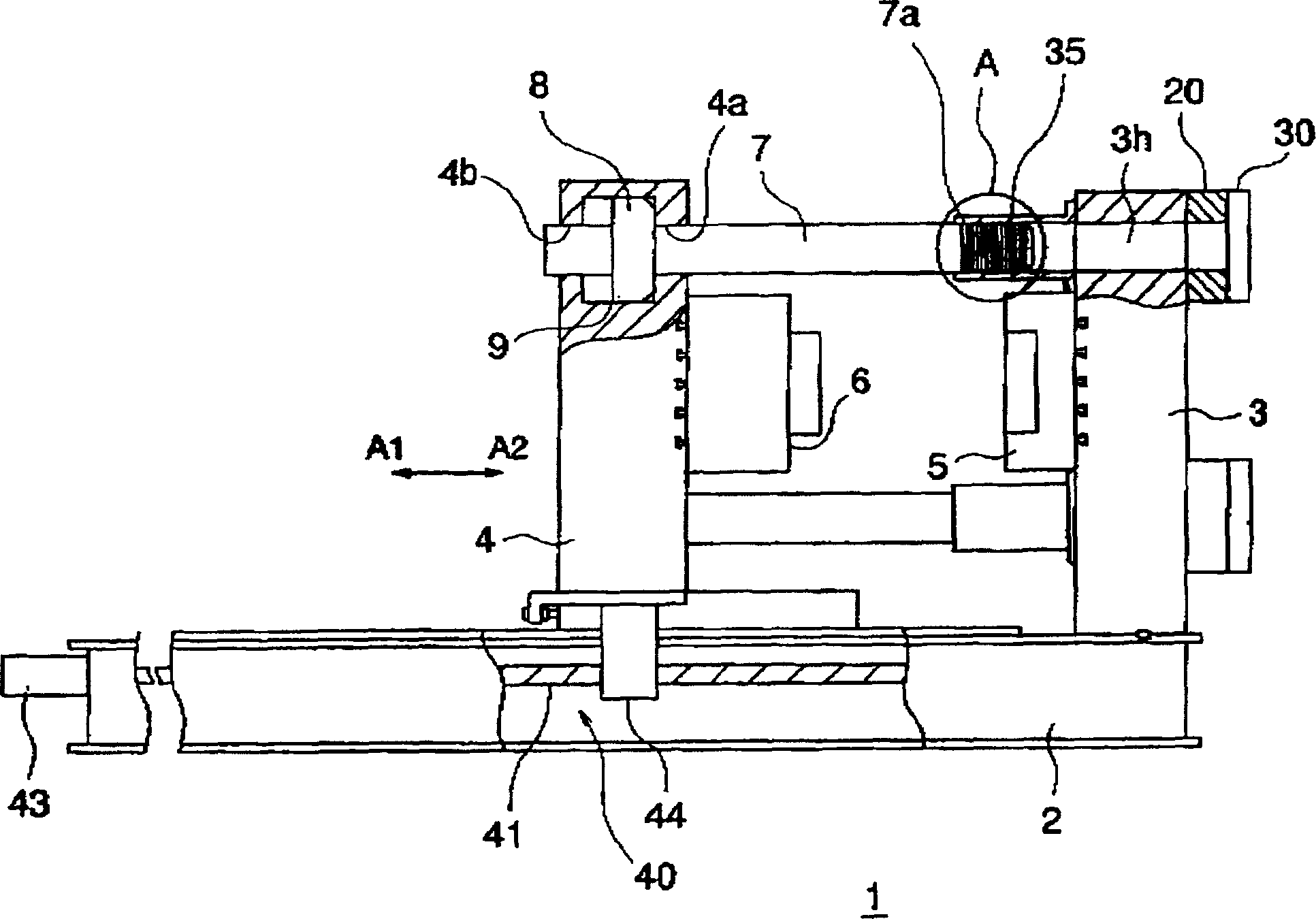
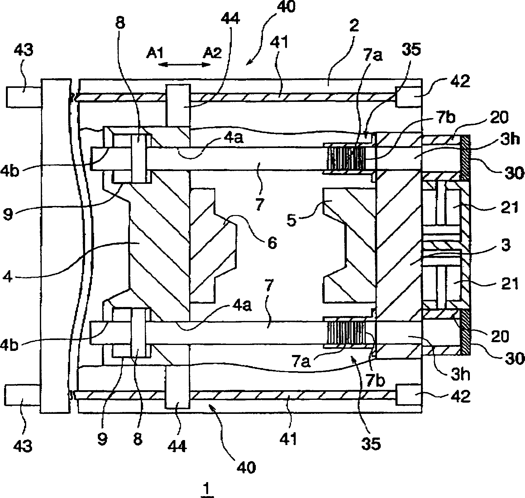
[0022] figure 1 is a diagram showing the structure of the mold clamping device according to the first embodiment of the present invention, figure 2 yes means figure 1 Horizontal cross-sectional view of the mold clamping device structure.
[0023] The mold clamping device 1 of this embodiment can be used, for example, in a die castingmachine.
[0024] Such as figure 1 and figure 2 As shown, the mold clamping device 1 has: a base 2, a fixed plate 3 and a movable plate 4, a pair of pull rods (connecting rods) 7,7, a pair of mold clamping oil cylinders 9,9, a pair of moving mechanisms 40,40, a A pair of split nuts 20 , 20 , a pair of contact members 30 , 30 and a pair of guide portions 35 , 35 .
[0025] And the fixed plate 3 is the fixed plate of the present invention, the movable plate 4 is the movable plate of the present invention, the pull bar 7 is the pull bar of the present invention, the mold clamping oil cylinders 9 and 9 are the mold clamping oil cylinders of the...
no. 2 example
[0081] refer to Figure 10 ~ Figure 17 The second embodiment of the mold clamping device of the present invention will be described.
[0082] Figure 10 is a diagram showing the structure of the mold clamping device according to the second embodiment of the present invention, Figure 11 yes means Figure 10 Horizontal cross-sectional view of the mold clamping device structure.
[0083] The mold clamping device 1A of the second embodiment is used for a die castingmachine as in the first embodiment.
[0084] Differences between the mold clamping device 1 of the first embodiment and the mold clamping device 1A of the second embodiment will be described.
[0085] exist figure 1 and figure 2 In the illustrated first embodiment of the mold clamping device 1 , the pistons 8 , 8 and the mold clamping cylinders 9 , 9 are provided on the movable platen 4 side. In contrast, in Figure 10 and Figure 12 In the mold clamping device 1A shown in the figure, pistons 8, 8 and cylind...
PUM
Abstract
A mold clamping apparatus able to shorten the cycle time required for mold opening and clamping operations and enabling easy pullout of tie bars, provided with a fixed die plate for holding a fixed die, a moveable die plate for holding a moveable die plate and provided movable in mold opening / closing directions A1,A2, tie bars provided with linking parts at their free ends and supported by the moveable die plate, clamping cylinders provided at the moveable die plate and driving the moveable die plate relative to the tie bars, movement mechanisms for making the moveable die plate move in the mold opening / closing directions A1,A2 and opening and closing the dies, contacting members against which the free ends of the tie bars contact so as to position the tie bars at predetermined positions with respect to the fixed die plate, and half nuts for linking with linking parts of the tie bars positioned at the predetermined positions and linking the tie bars with the fixed die plate.
Description
technical field [0001] The present invention relates to a mold clamping device used in molding devices such as die casting machines and plastic injection molding machines. Background technique [0002] Forming devices such as die-casting machines and plastic injection molding machines, for example, inject molding materials to the mold to fill the mold cavity formed when the moving mold and the fixed mold are molded together. [0003] As a mold clamping device for such mold clamping, there are known, for example, an elbow type mold clamping device, a direct pressure type mold clamping device, a compound type mold clamping device, and the like. [0004] As disclosed in JP-A-10-52841, JP-5-7419, and JP-5-49330, the composite mold clamping device is equipped with a transmission for moving the movable plate relative to the fixed plate to open and close the mold. Device and transmission device for mold clamping. [0005] As the above-mentioned composite mold clamping device, the...
Claims
Application Information
Patent Timeline
Application Date:The date an application was filed.
Publication Date:The date a patent or application was officially published.
First Publication Date:The earliest publication date of a patent with the same application number.
Issue Date:Publication date of the patent grant document.
PCT Entry Date:The Entry date of PCT National Phase.
Estimated Expiry Date:The statutory expiry date of a patent right according to the Patent Law, and it is the longest term of protection that the patent right can achieve without the termination of the patent right due to other reasons(Term extension factor has been taken into account ).
Invalid Date:Actual expiry date is based on effective date or publication date of legal transaction data of invalid patent.

