Asymmetric damping tensioner belt drive system

A technology of transmission system and tensioning wheel, which is applied in the direction of gear transmission, transmission, belt/chain/gear, etc., and can solve problems such as belt tension that cannot be completely solved

A technology of transmission system and tensioning wheel, which is applied in the direction of gear transmission, transmission, belt/chain/gear, etc., and can solve problems such as belt tension that cannot be completely solved

CN1554000AInactive Publication Date: 2004-12-08THE GATES CORP

Image

  • Asymmetric damping tensioner belt drive system
  • Asymmetric damping tensioner belt drive system
  • Asymmetric damping tensioner belt drive system

Examples


Embodiment Construction

[0060] DETAILED DESCRIPTION OF THE PREFERRED EMBODIMENT

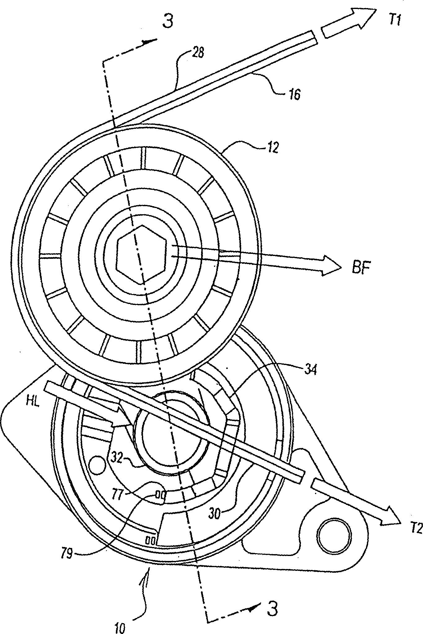
[0061] Described here are tensioning pulleys with asymmetric damping characteristics. Assuming that the asymmetric tensioner and the ordinary tensioner have the same tensioner force, the asymmetric tensioner consumes more energy than the ordinary tensioner. Another major advantage of an asymmetric tensioner is that it can provide a higher degree of damping for a given belt drive system than a normal tensioner.

[0062] There are two main differences in the operation of an asymmetric tensioner and a normal tensioner. First, in the half-cycle of the tensioner loaded, the frictional force of the asymmetric tensioner and thus the vibration energy consumed is significantly higher than the frictional force and energy of the unloaded half-cycle of the tensioner. For ordinary tensioners, these forces are basically equal. Secondly, due to the partial damping function of the tensioner, the belt drive energy is only dissipated ...


PUM


Abstract

The invention comprises an asymmetric damping tensioner system for belt drives on an engine. A belt is connected between a driver pulley on a crankshaft and any number of driven pulleys. Each drive pulley is connected to an accessory such as an alternator, power steering pump, compressor or the like. The tensioner is placed anywhere before the first component of significant effective inertia, in the belt movement direction. A biasing member in the tentioner is used to maintain a tention in the belt. The tensioner further comprises a damping mechanism to damp belt vibrations caused by the operation of the engine. Tensioner damping friction is unequal or asymmetric, depending upon the direction of movement of the tentioner arm. During acceleration the damping friction of the tentioner in the unloading direction is significantly lower than the damping friction in the opposite, or loading direction, as is the case during deceleration. Lower damping friction during acceleration allows the tensioner arm to quickly adjust to the increase in belt length caused by acceleration. Higher damping friction during deceleration prevents the tensioner arm from being moved too far in the loading direction thereby causing slipping and noise. Asymmetric damping also significantly diminishes overall vibration in the belt during all phases of operation.

Description

Field of Invention [0001] The present invention relates to a front end accessory drive, and more particularly to a belt drive system with asymmetrically damped tensioning pulleys. Background of the Invention [0002] Most engines used in automobiles and the like include multiple belt-driven accessory systems that are necessary for the vehicle to function properly. Accessory systems may include alternators, air conditioner compressors, and power steering pumps. [0003] The accessory system is usually mounted on the front face of the engine. Each attachment has a pulley mounted on a shaft to receive power from some form of belt drive. In earlier systems, each attachment was driven by a single belt running between the attachment system and the crankshaft. Due to improvements in belt technology, a single serpentine belt is now commonly used in most applications. A single serpentine belt that weaves between the appendages drives the appendages. The engine crankshaft drives ...

Claims


Application Information

Patent Timeline
08 Dec 2004
Publication
CN1554000A
IPC
F16H1/00; F16H7/08; F16H7/12
CPC
F16H7/1218; F16H2007/084; F16H2007/081; F16H7/00
Inventors
刘克铭; 亚历山大·塞基