Friction transmission type rotation driving device

A technology of rotary drive and friction transmission, applied in friction transmission, transmission, differential transmission, etc., can solve the problems of assembling the brake into the friction transmission, the cost is disadvantageous, etc., to reduce the manufacturing cost and prevent the manufacturing Effect

Inactive Publication Date: 2004-12-15
SUMITOMO HEAVY IND LTD
View PDF0 Cites 0 Cited by
  • Summary
  • Abstract
  • Description
  • Claims
  • Application Information

AI Technical Summary

Problems solved by technology

[0022] This situation means that the result will be cost disadvantageous for products formed by assembling brakes into other transmissions such as gears, which in turn is considered to be an impossibility to incorporate brakes into friction transmissions until now. the reason in

Method used


Image

  • Friction transmission type rotation driving device
  • Friction transmission type rotation driving device
  • Friction transmission type rotation driving device

Examples


Embodiment Construction

[0079] Hereinafter, embodiments of the present invention will be described in detail with reference to the drawings.

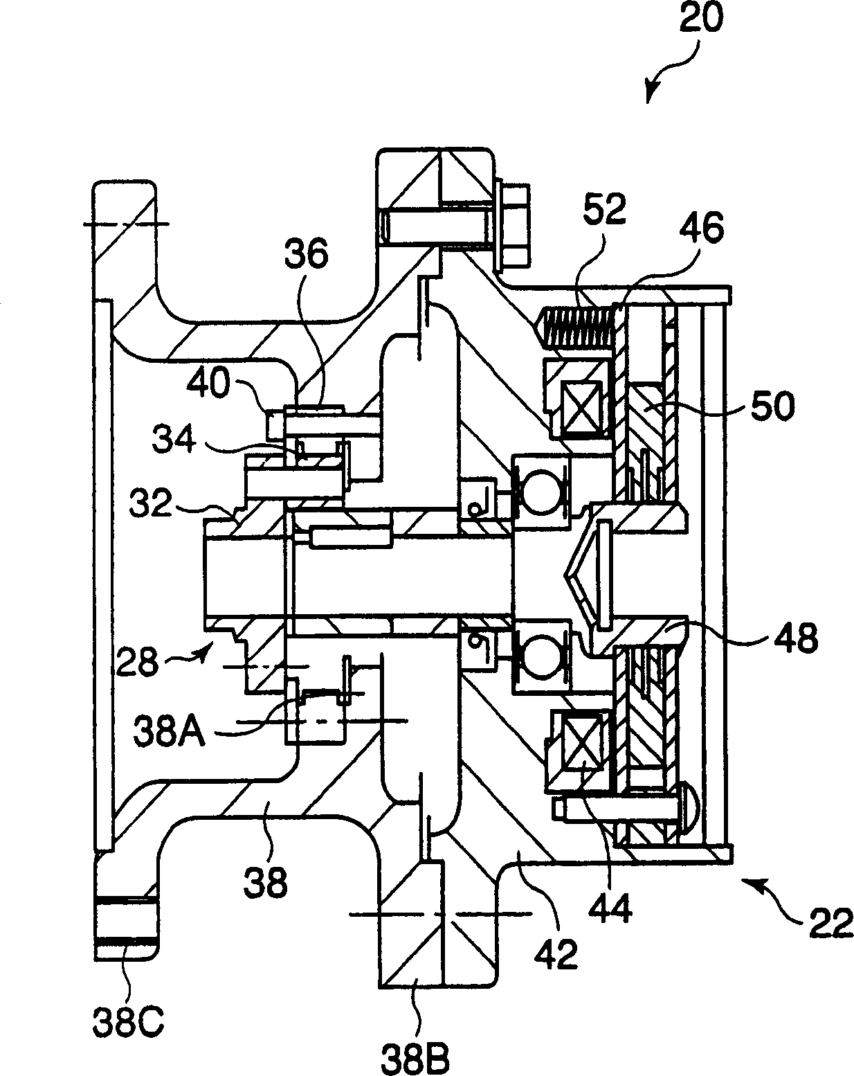
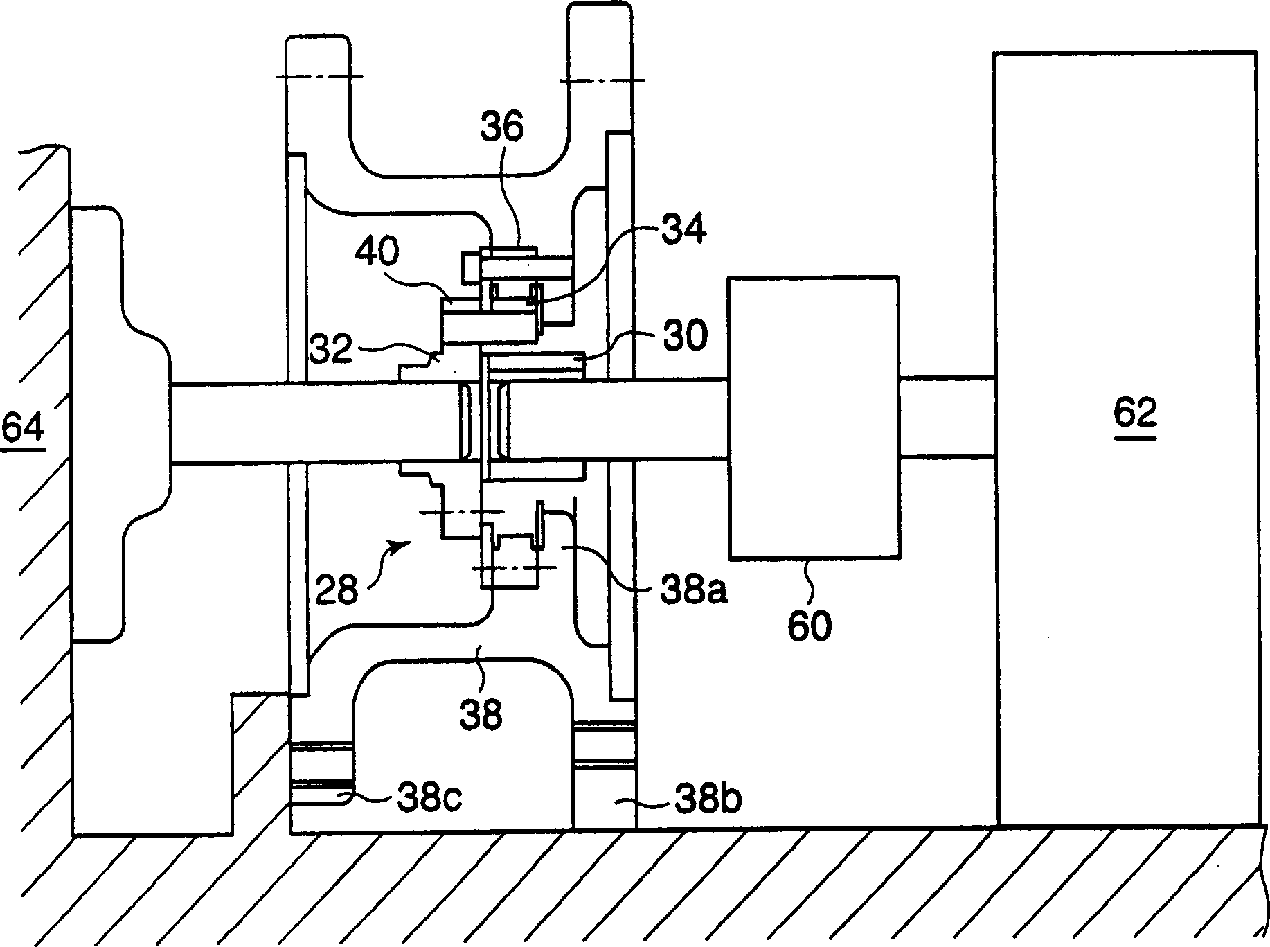
[0080] figure 1 It is a partial cross-sectional view showing a friction transmission device 20 according to an embodiment of the present invention. The friction transmission is equipped with a simple planetary roller mechanism 28 as friction rollers with a sun roller 30, a planetary roller 34 and a ring roller 36, which are held on the transmission gear and are in rotational contact with the outer circumference of said sun roller, which the planetary rollers are in rotational contact with the inner circumference of the ring roller while limiting the ring roller's own rotation; and

[0081] The brake 22 is connected with the sun roller 30 and brakes the rotation of the sun roller 30 .

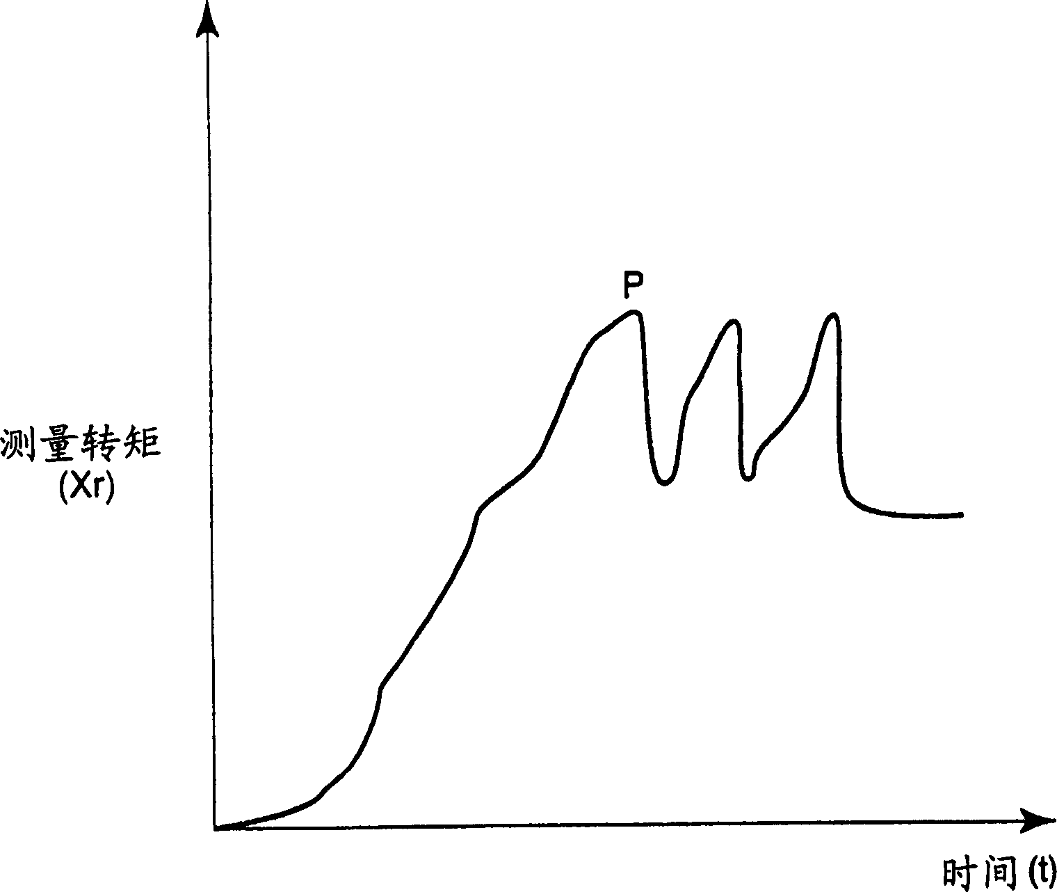
[0082] The static friction torque Y obtained from the brake is set to 0.1Xd


PUM


Abstract

A frictional transmission apparatus comprising a simple planetary roller mechanism and a brake mechanism, the simple planetary roller mechanism having friction rollers including a sun roller, a planetary roller, and a ring roller. Static friction torque Y obtainable from the brake mechanism is set to set to satisfy Y F16H 13/06 F16H 13/08 9 18 1 2000/12/4 1554877 2004/12/15 000000000 Sumitomo Heavy Industries Japan Tamenaga Jun Minegishi Kiyoji zeng xiangling 72001 The Company Ltd. of the Chinese Patent Agency (Hong Kong) Zi Building 22, Yingjun Centre, No.23, Gangwan Road, Hong Kong Wanzi Japan 1999/12/3 344887/99 Japan 1999/12/3 344888/99 Japan 1999/12/3 345243/99

Description

technical field [0001] The invention relates to a friction transmission rotary drive. Background technique [0002] Friction drives with simple planetary roller mechanisms have long been known. [0003] exist Figure 8 An example of such a conventional friction transmission is schematically drawn in . The friction transmission device 1 is equipped with a sun roller 2, a planetary roller 6 in rotational contact with the outer circumference of the sun roller 2, and a planetary roller 6 on its inner circumference in the housing 9 (not entirely drawn) of the simple planetary roller mechanism 10 The ring roller 8 which is in contact with the upper rotation and at the same time limits its own rotation. In addition, the gear 4 is connected to the simple planetary roller mechanism 10 by inserting support pins into the planetary rollers 6 . [0004] The friction conventional device 1 has a sun roller 2 or a gear 4 as a power input / output element and a ring r...

Claims


Application Information

Patent Timeline
Patent Type & Authority Applications(China)
IPC IPC(8): F16H13/08F16H48/06H02K7/102H02K7/116
CPCH02K7/1025F16H13/06H02K7/116F16H13/08
Inventor 峰岸清次为永淳
Owner SUMITOMO HEAVY IND LTD
Why Eureka
Try Eureka