
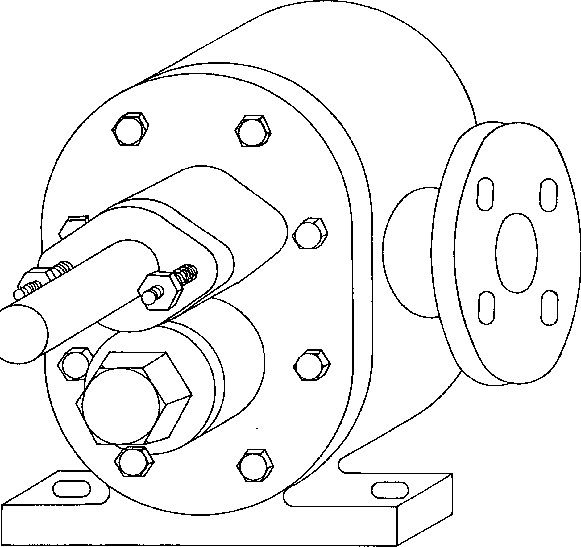
Method of eradicating axial leakage of gear wheel pump

A gear pump, axial technology, applied in pumps, engine seals, rotary piston pumps, etc., can solve problems such as reduction of suction lift, and achieve the effect of reducing suction lift and solving leakage

Inactive Publication Date: 2004-12-22
荆平平
View PDF0 Cites 0 Cited by
  • Summary
  • Abstract
  • Description
  • Claims
  • Application Information

AI Technical Summary

Problems solved by technology

It not only completely solves the leakage of liquid to the outside of the pump, but also effectively solves the defect of reduced suction due to air leakage

Method used


Image

  • Method of eradicating axial leakage of gear wheel pump
  • Method of eradicating axial leakage of gear wheel pump

Examples


Embodiment Construction

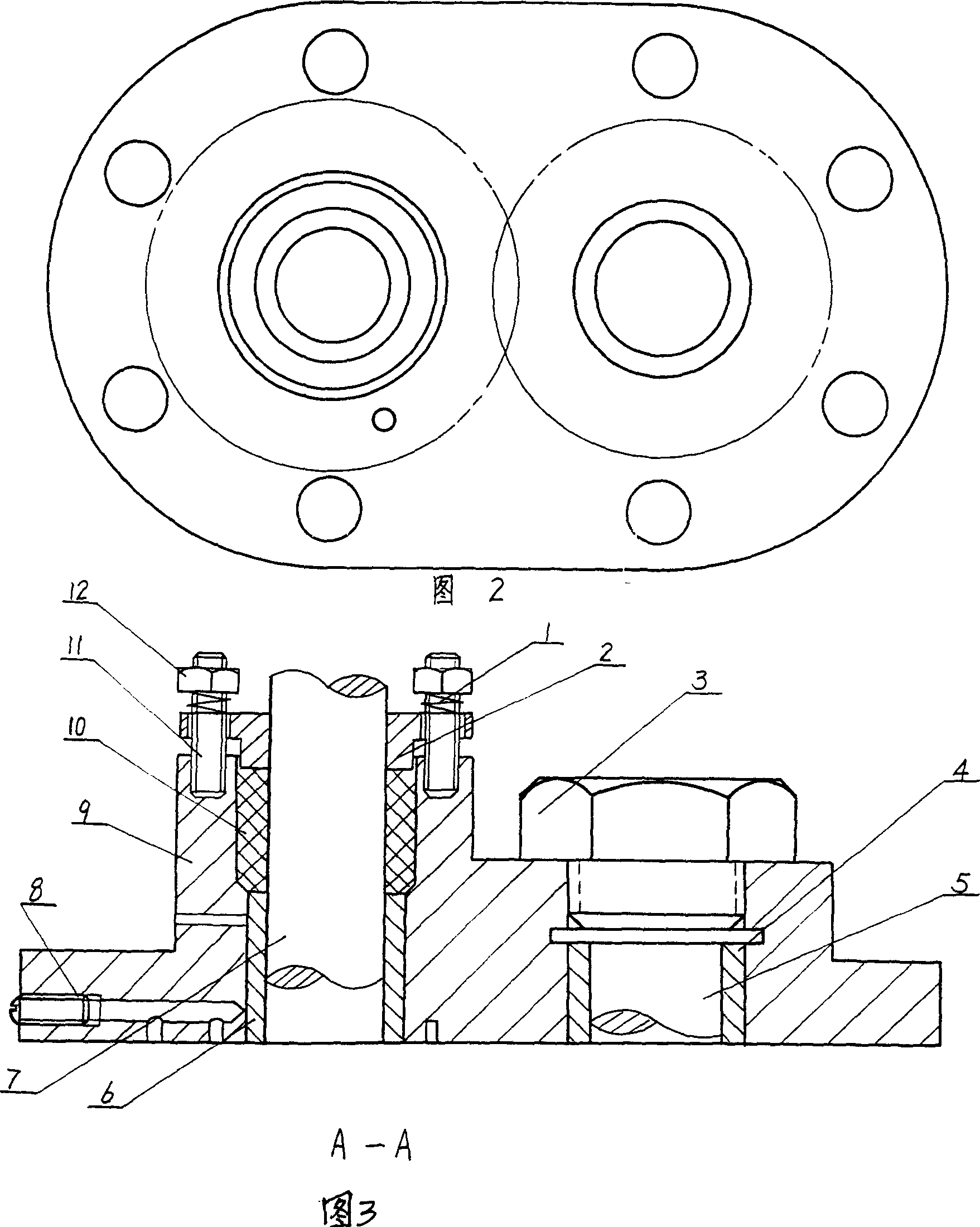
[0011] In the view of Figure 3A-A, add a ring groove concentric with the shaft hole around the inner plane driving wheel shaft hole of the pump cover (9), and drill a deep pump cover vertically within the suction range of the corresponding pump outside the groove For the small hole in the center of the thickness, drill a straight through hole on the outer end surface of the pump cover to connect the small hole in the suction range outside the groove with the annular groove, and plug the hole on the outer end surface of the pump cover with a plug (8). Then put the driving wheel shaft (7) and the driven gear shaft (5) into the left upper sleeve (6) and right upper sleeve (4) respectively, and fix the pump cover (9) to the pump body with bolts Put the sealing material (10) into the stuffing bin, press on the gland (2) of the stuffing bin, then screw on the plugging bolt (11), put on the compression spring (1), tighten with the nut (12), and finally Screw on the blocking nut (3) above...


PUM


Abstract

An annular groove concentric to shaft hole is added around shaft hole of driving wheel on inner plane of pump cover. A vertical pinhole within suction region outside the said groove is drilled to depth to center of thickness of pump cover. A through hole is drilled on external end face of the pump cover, making the pinhole connect to the annular groove. Then, on external end face, through hole is plugged up by a pipe plug. Sealant material is put into stuffing storeroom around shaft hole of driving wheel, and pressing cover, screwing on bolt, putting pressure spring and screwing on nut. The method eliminates leakage, reaches self-sealing and solves disadvantage of reduced suction lift caused by air leak.

Description

Technical field [0001] The invention relates to a pump, in particular to a gear pump for conveying high-temperature liquid. Background technique [0002] At present, gear pumps vary in size and shape, but their basic principles and structures are all mechanical power drive shafts. Through the drive wheel shaft hole on the pump cover, the driving gear rotor meshing with the driven gear rotor is driven to complete the liquid delivery. During the working process, the liquid whose pressure rises within the head range of the pump will always pass through the movement gap between the end face of the driving gear rotor and the pump cover, and leak to the outside of the pump along the movement gap between the drive shaft and the shaft hole. Similarly, the negative pressure in the suction range of the pump also keeps the air always passing through the movement gap between the drive shaft wheel hole and the shaft, passing through the movement gap between the end face of the gear rotor and ...

Claims


Application Information

Patent Timeline
IPC IPC(8): F04C2/14F16J15/16
Inventor 荆平平柴洪泽荆学松
Owner 荆平平
Learn More