Mop with liquid-sprayer

A mop and mop handle technology, which is applied in the field of sanitary ware, can solve the problems such as the inability to adjust the spray angle, the inability to meet the needs of fine-tuning, and the limitation of the spray range, and achieve the effect of expanding the spray angle range, compact structure, and beautiful appearance

Inactive Publication Date: 2005-01-05
李爱良
View PDF1 Cites 8 Cited by
  • Summary
  • Abstract
  • Description
  • Claims
  • Application Information

AI Technical Summary

Problems solved by technology

The defects of this liquid spray mop are as follows: 1. After the large spring parameters are determined, the size of the liquid output and the speed of the liquid output are determined, which cannot be adjusted, and cannot meet the fine-tuning needs of the function; 2. The nozzle is located on the base , so that the spray range is limited, and the spray angle cannot be adjusted

Method used


Image

  • Mop with liquid-sprayer
  • Mop with liquid-sprayer
  • Mop with liquid-sprayer

Examples


Embodiment Construction

[0017] The present invention will be described in detail below in conjunction with the accompanying drawings and embodiments.

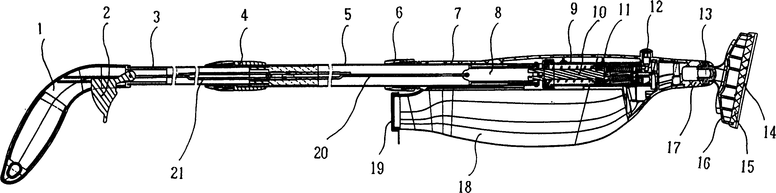
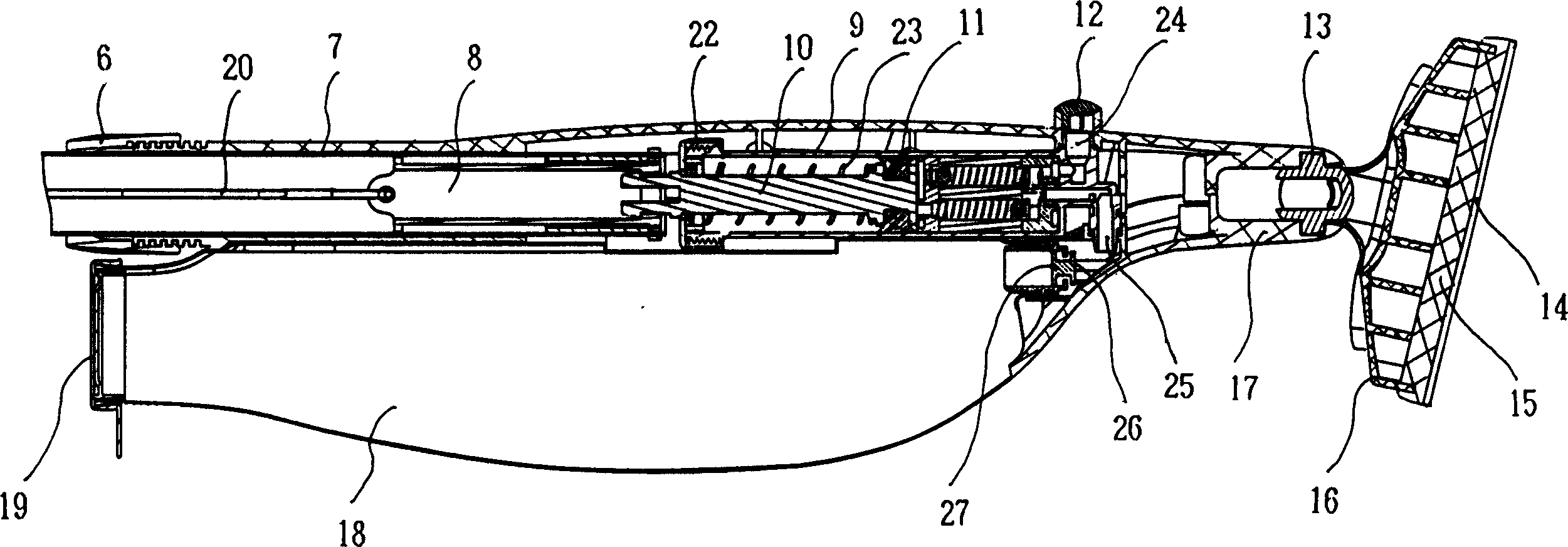
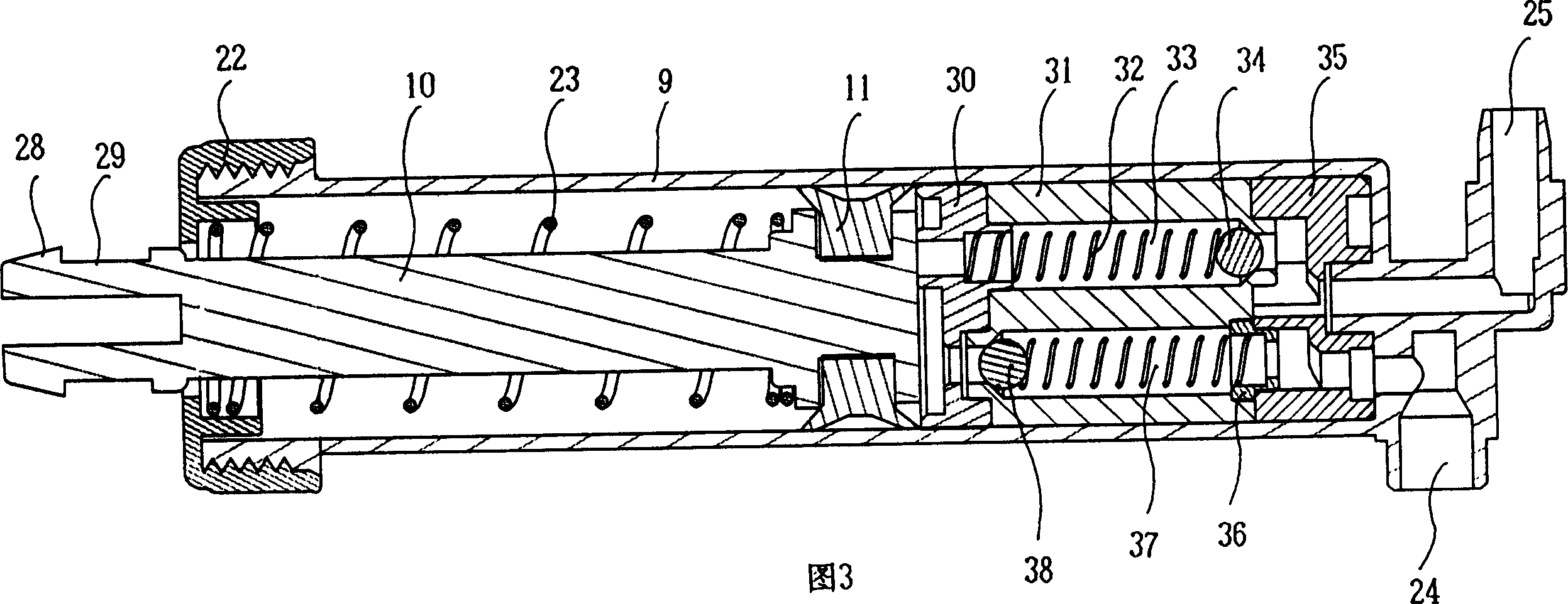
[0018] Such as figure 1 - As shown in Figure 3, the liquid spray mop is composed of a mop handle, a liquid spray device and a cleaning part.

[0019] The mop handle consists of an inner rod 3 and an outer rod 5 that are mutually fitted and retractable. After elongation, the male and female locking sleeves 4 are locked. 1 The lower side has a window for the pulling range of the liquid spray switch 2 in the liquid spray device.

[0020] The liquid spraying device is made up of operating mechanism, liquid suction and discharge mechanism, liquid storage bottle 18.

[0021] The operating mechanism is located in the hollow inner rod 3 and the outer rod 5 of the mop handle, and one end of the liquid spray switch 2 is exposed for pulling manipulation, and the inner end is connected to the front drag hook 21, the front drag hook 21 and the rear drag hook 20,...


PUM


Abstract

A mop able to spray liquid is composed of mop handle, liquid spraying unit consists of liquid spray manipulating mechanism, liquid sucking-discharging mechanism and liquid storage bottle, and cleaning part. The amount of sprayed liquid and the speed and direction of spraying liquid are controll able.

Description

technical field [0001] The invention relates to a sanitary appliance, in particular to a liquid spray mop with a liquid spray function. Background technique [0002] The mop is an indispensable cleaning tool for families, hotels, shopping malls, and offices. It is an environmental beautician, especially a liquid spray mop with a liquid spray function. It can spray some water or clean the floor anytime and anywhere according to the requirements for floor cleaning Essence and other cleaning liquids are easy to wipe off the ground stains, which can better meet people's requirements than a mop without a liquid spray device. The "liquid spray mop" of Chinese patent 02292487.6 includes a mop handle, a liquid spray device and a cleaning part. The liquid spray pump of the liquid spray device adopts a pump body and a piston structure, and each is connected to the liquid inlet, the The liquid outlets are connected, the bottle cap is arranged on the liquid storage bottle, and the nozz...

Claims


Application Information

Patent Timeline
Patent Type & Authority Applications(China)
IPC IPC(8): A47L13/22
Inventor 李爱良
Owner 李爱良
Why Eureka
Try Eureka