Method for connecting space object positioned by visible marking points

A technology of space objects and marking points, which is applied in surgical operations and other detection and positioning occasions, space objects, and new marking point positioning fields. The effect of reducing the amount of error

Inactive Publication Date: 2005-01-05
SHANGHAI JIAO TONG UNIV
View PDF0 Cites 37 Cited by
  • Summary
  • Abstract
  • Description
  • Claims
  • Application Information

AI Technical Summary

Problems solved by technology

The accuracy of this positioning method is limited by the manufacturing process of the probe, and it is very difficult to ensure that the centers of the three spherical markers are collinear with the probe tip

Method used


Image

  • Method for connecting space object positioned by visible marking points
  • Method for connecting space object positioned by visible marking points
  • Method for connecting space object positioned by visible marking points

Examples


Embodiment Construction

[0018] In order to better explain the technical solution of the present invention, a further detailed description will be made below in conjunction with the accompanying drawings and embodiments.

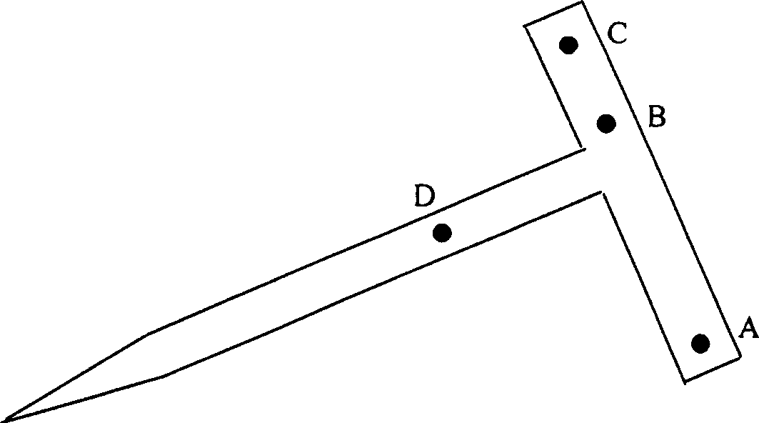
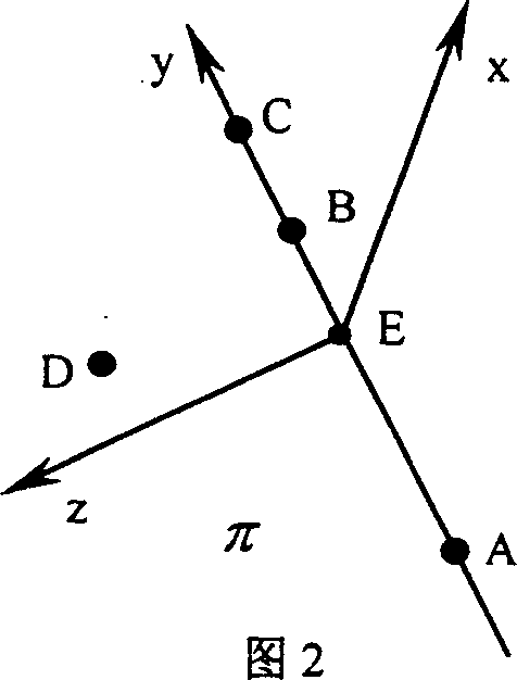
[0019] 1. The probes used in the method of the present invention are as figure 1 shown. The four points A, B, C, and D are the positions of the marker points, and the three points A, B, and C are collinear (it does not need to be strictly implemented). Establish a coordinate system based on the four points A, B, C, and D on the probe, which is called the probe coordinate system. Once a method of establishing a coordinate system is specified, the coordinate system established by four points is unique. Figure 2 is a schematic diagram of establishing the coordinate system of the probe. The plane where A, C, and D are located is recorded as π, and the main optical axis of the camera is required to be outside the plane π. Four marker points are extracted from the image according to the...


PUM


Abstract

A method for using visual marker point to locate the 3D object to be connected includes such steps as creating a coordinate system of probe by 4 marker dots, determining the coordinate of probe tip in the coordinate system, calculating the relation between the coordinate systems of world and probe, and coordinate transforming to obtain the coordinate information of probe tip in world coordinate system.

Description

technical field [0001] The invention relates to a method for locating connected space objects by observable marking points, which is a new type of marking point locating method based on machine vision technology, and can be used in surgical operations and other detection and positioning occasions. It belongs to the field of advanced manufacturing and automation (medicine). Background technique [0002] Since the mid-1980s, machine vision technology has gradually matured, and people can perceive and obtain the shape and position information of occluded objects on many occasions. This is of great significance to neurologists - it is difficult to determine the location of brain lesions has always been a technical problem in brain surgery, and the probe positioning method using the principle of machine vision can solve this problem within a certain range of accuracy requirements [Zhang Ke, Tang Long. Interaction techniques in computer-simulated surgery. Chinese Medical Inform...

Claims


Application Information

Patent Timeline
Patent Type & Authority Applications(China)
IPC IPC(8): A61B90/00
Inventor 刘允才罗毅刘宏建
Owner SHANGHAI JIAO TONG UNIV
Why Eureka
Try Eureka