Push-in type clamping head bending die device in middle frame of cold frame bender

A kind of cold bending machine, embedded technology, applied in the direction of transportation and packaging, ship parts, ships, etc., can solve the problems of the space reduction of the upper chuck lifting, inconvenient operation of the line, and huge structure, so as to improve the lifting distance and function Improve and increase the effect of visual space

Inactive Publication Date: 2005-01-12
WUHAN UNIV OF TECH
View PDF0 Cites 4 Cited by
  • Summary
  • Abstract
  • Description
  • Claims
  • Application Information

AI Technical Summary

Problems solved by technology

In this part, the guide mechanism is arranged below the cylinder barrel. The upper chuck slides up and down inside the guide frame, and all its horizontal force is transmitted to the middle frame through the guide mechanism, making the whole structure huge and complicated.
Moreover, when clamping the rib profile, in order to reduce the moment arm of the horizontal force, the guid

Method used


Image

  • Push-in type clamping head bending die device in middle frame of cold frame bender
  • Push-in type clamping head bending die device in middle frame of cold frame bender

Examples


Embodiment Construction

[0009] Below in conjunction with accompanying drawing and specific embodiment the present invention is described in further detail:

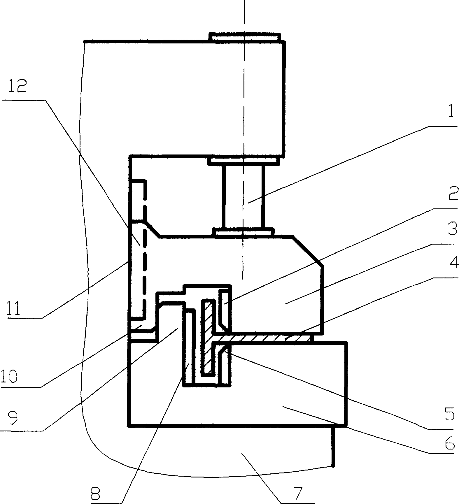
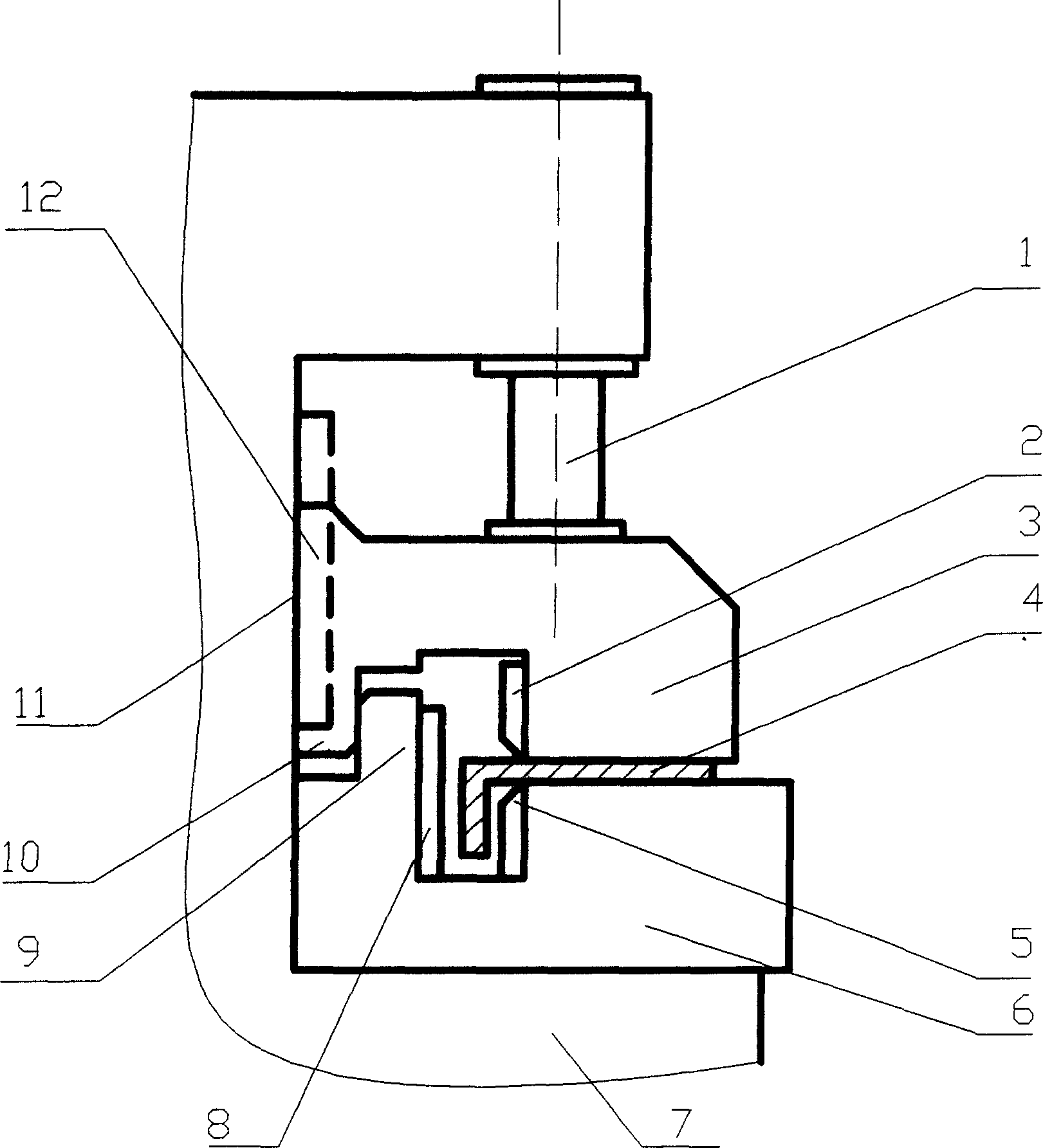
[0010] Such as figure 1 The middle frame embedded chuck bending die device of the rib cold bending machine for processing T-shaped rib profile 4 includes the middle frame 7, the top of the middle frame 7 is vertically installed with the middle clamping oil cylinder 1, and the middle clamping oil cylinder The driving end of the lower plunger of 1 is connected with the upper chuck 3, and the rear part of the upper chuck 3 is connected with the vertical guide mechanism 12. The vertical guide mechanism 12 adopts a simple and common rail structure, and is fixedly installed between the upper chuck 3 and the middle The vertical sliding contact surface of the frame 7 is the guide surface 11 of the vertical guide mechanism 12, and the upper chuck 3 can move up and down along the guide surface 11. A lower chuck 6 is arranged below the upper chuck 3, and ...


PUM


Abstract

An embed-type chuck-bending die unit for the middle frame of cold rib bender is disclosed. An upward convex table behind the lower chuckand a guide mechanism on middle frame constitute a recess. a downward convex table is driven by the clamping cylinder to move downward for pushing the clamped rib in said recess. The reactive force of said rib is transferred from the down convex table to upper one, so improving the stressed state of upper chuck.

Description

technical field [0001] The invention relates to a rib cold bending machine suitable for processing curved-shaped components on a ship in shipbuilding equipment, in particular to a middle frame embedded chuck bending die device of a rib cold bending machine. Background technique [0002] The bending die device of the middle frame chuck of the rib cold bending machine needs to apply a large bending force to the rib profile when bending T-shaped, L-shaped or other types of rib profiles. When the rib profile is bent outward, the positive horizontal bending force is applied to the rib profile by the rear bending die of the lower chuck, and the web edge of the rib profile is pulled at this time; when the rib profile is bent inwardly, the lower clamp The front bending die of the head applies a reverse horizontal bending force to the rib profile, or the front bending die of the lower chuck and the bending die of the upper chuck simultaneously apply a reverse ...

Claims


Application Information

Patent Timeline
IPC IPC(8): B21D11/00B63B9/00
Inventor 王呈方冷荣嘉茅云生周永清
Owner WUHAN UNIV OF TECH
Why Eureka
Try Eureka