
Panoramic camera

A camera and panoramic ring technology, applied in the field of panoramic cameras, can solve the problems of easy to produce jitter, unsuitable for panoramic shooting, low imaging resolution, etc.

Inactive Publication Date: 2005-01-12
尹红
View PDF0 Cites 6 Cited by
  • Summary
  • Abstract
  • Description
  • Claims
  • Application Information

AI Technical Summary

Problems solved by technology

In order to solve this problem, someone once designed a motorized scanner that can drive an ordinary camera to rotate, but this motorized scanner cannot take the rear node of the camera lens as the center of rotation, and it is prone to shake during the rotation process, so the imaging resolution is low. , not suitable as a professional tool for panorama shooting

Method used


Image

  • Panoramic camera
  • Panoramic camera
  • Panoramic camera

Examples


Embodiment Construction

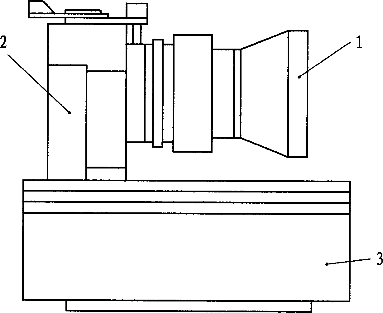
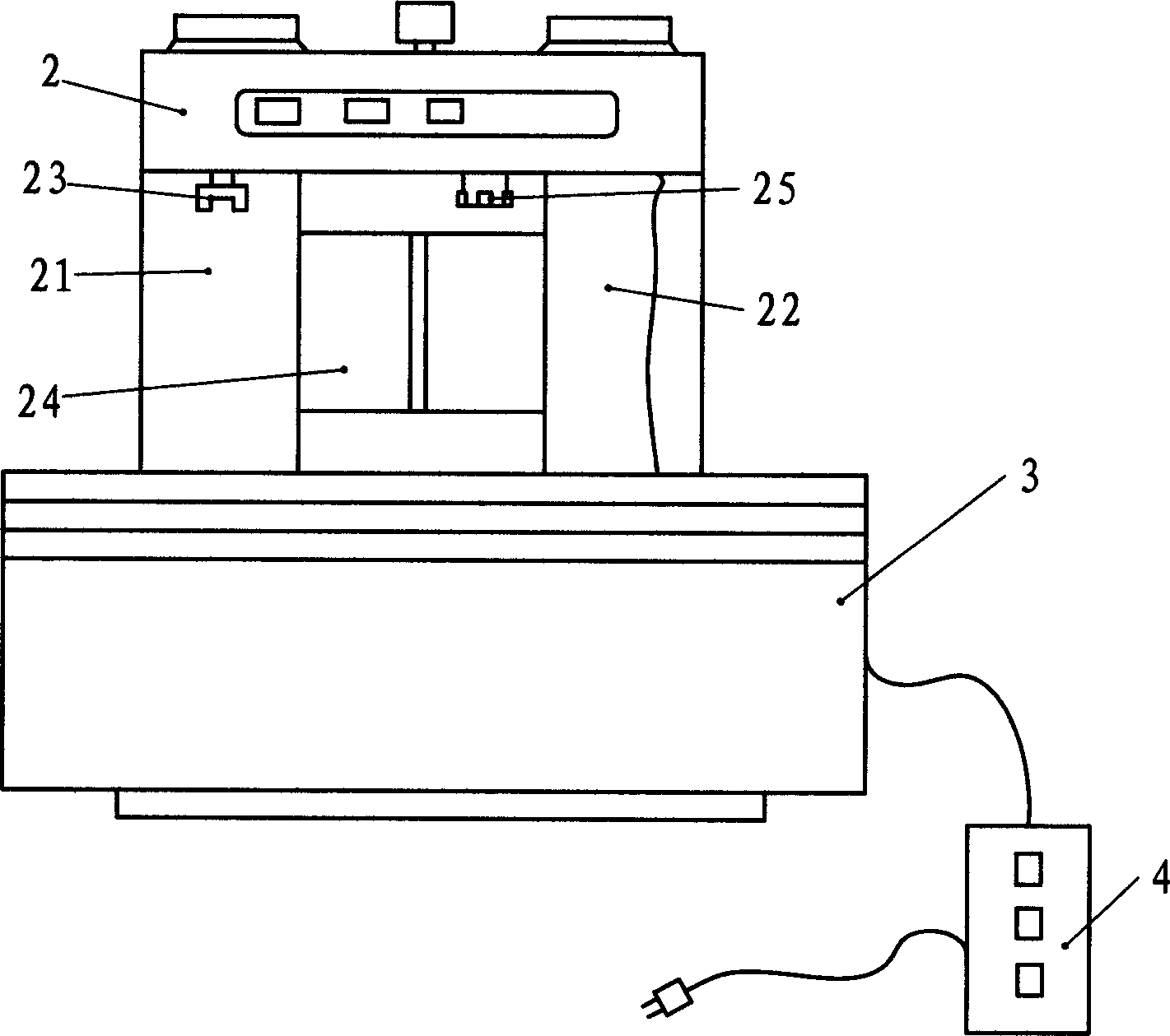
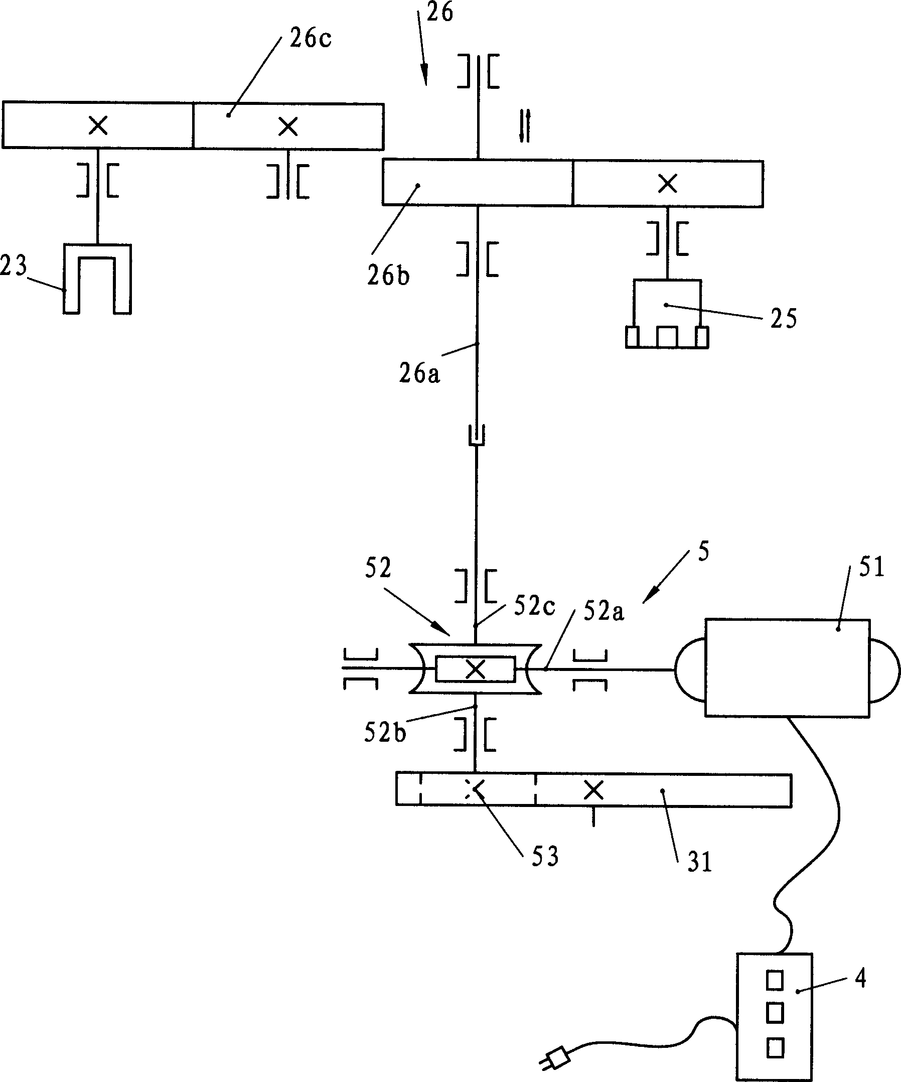
[0010] A panoramic ring camera, such as figure 1 As shown, it includes: a lens 1, the lens 1 is fixed on the body 2, and the lower part of the body 2 is provided with a base 3. Such as figure 2 As shown, one side (left side) of the fuselage 2 is provided with a first storage chamber 21 for containing unexposed films, and the other side (right side) is provided with a second storage chamber 22 for storing exposed films. The top of the film storage chamber 21 is provided with a rewinding shaft 23 that can rotate the film, and the middle part of the fuselage 2 is provided with an imaging plane 24, and the upper part of the imaging plane 24 is provided with a perforation that can move the film so that the film moves from the first film storage chamber 21 to The film conveying shaft 25 that the second storage chamber 22 moves has a slit-like exposure hole in the middle of the imaging plane 24, and the width of the exposure hole is preferably 0.8 mm to 1.5 mm. Inside the base 3 i...


PUM


Abstract

The camera includes following parts: lens, body for fixing the lens; there are first cavity for storing unexposed film and second cavity for storing exposed film inside body; backrolling shaft is on top end of the first cavity for storing unexposed film; slot type exposal aperture is on imaging plane in middle part of the body; film transport shaft is on top part of the imaging plane; first gearing inside lower body is capable of driving body to rotate 360 degrees horizontally around rear nodal point; first gearing can be inserted into second gearing to transfer torsional moment, the said second gearing makes backrolling shaft or transport shaft rotate in reverse orientation. Features are high resolution, not easy of wobble.

Description

technical field [0001] The invention relates to the technical field of cameras, in particular to a panoramic camera capable of realizing panoramic shooting around 360°. Background technique [0002] The shooting of large groups or large scenes requires 360° panoramic shooting, and ordinary cameras can only be shot in sections and then stitched together, so the quality of the photos taken cannot be guaranteed. In order to solve this problem, someone once designed a motorized scanner that can drive an ordinary camera to rotate, but this motorized scanner cannot take the rear node of the camera lens as the center of rotation, and it is prone to shake during the rotation process, so the imaging resolution is low. , not suitable as a professional tool for panorama shooting. Contents of the invention [0003] The object of the present invention is to provide a panorama ring camera that is not easy to shake, has high imaging resolution, and is easy to use and can realize panoram...

Claims


Application Information

Patent Timeline
Patent Type & Authority Applications(China)
IPC IPC(8): G03B17/00G03B37/00
Inventor 尹红
Owner 尹红
Learn More