

Flashing method of non-service cut-off of light transmission of link network
An optical transmission, chain-type technology, applied in the field of optical transmission, can solve the problem of difficult to guarantee uninterrupted services, and achieve the effect of simple operation process
- Summary
- Abstract
- Description
- Claims
- Application Information
AI Technical Summary
Problems solved by technology
Method used
Image

Examples
Embodiment Construction
[0036] The present invention will be further described in detail below in conjunction with the accompanying drawings and embodiments.
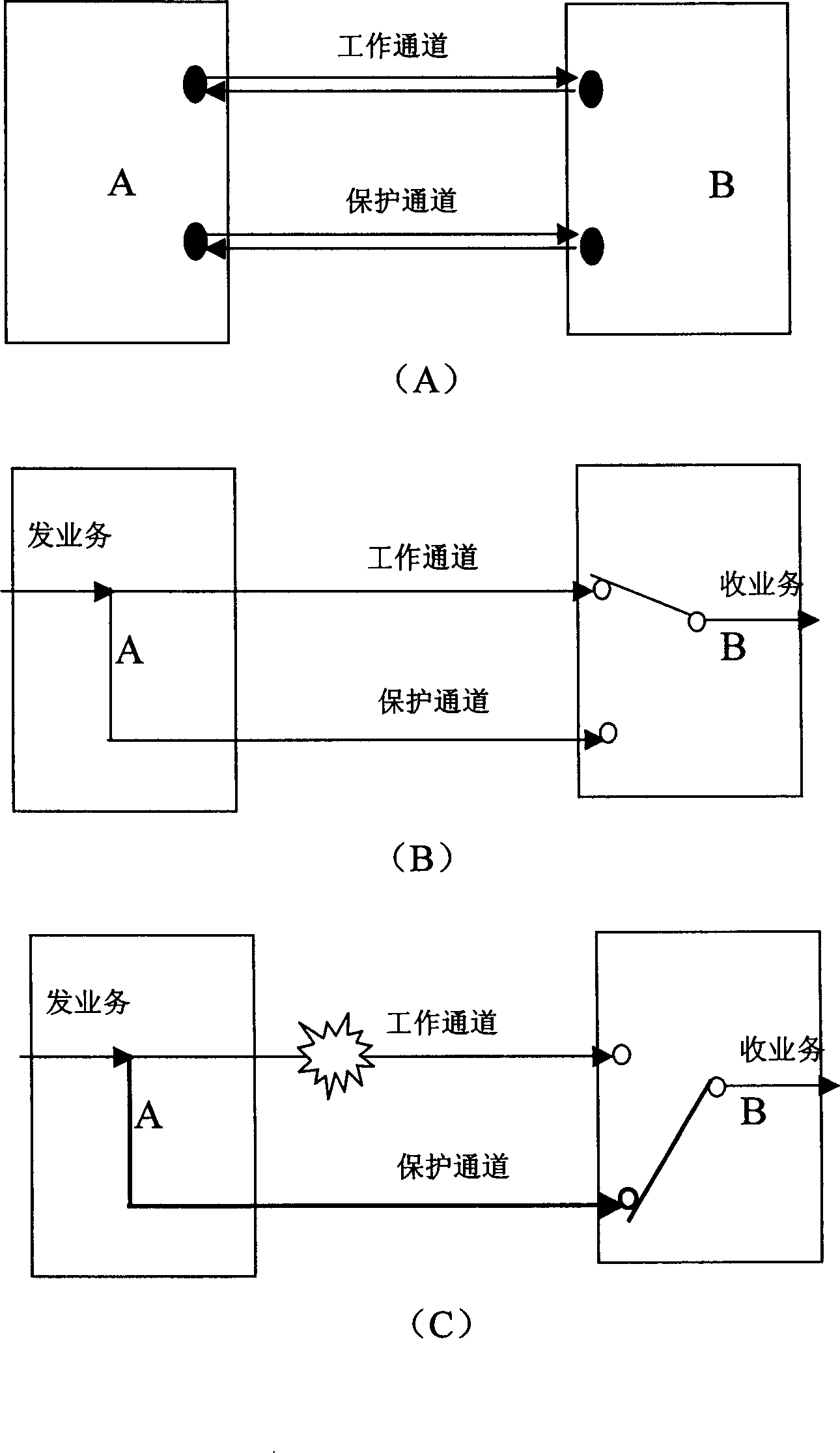
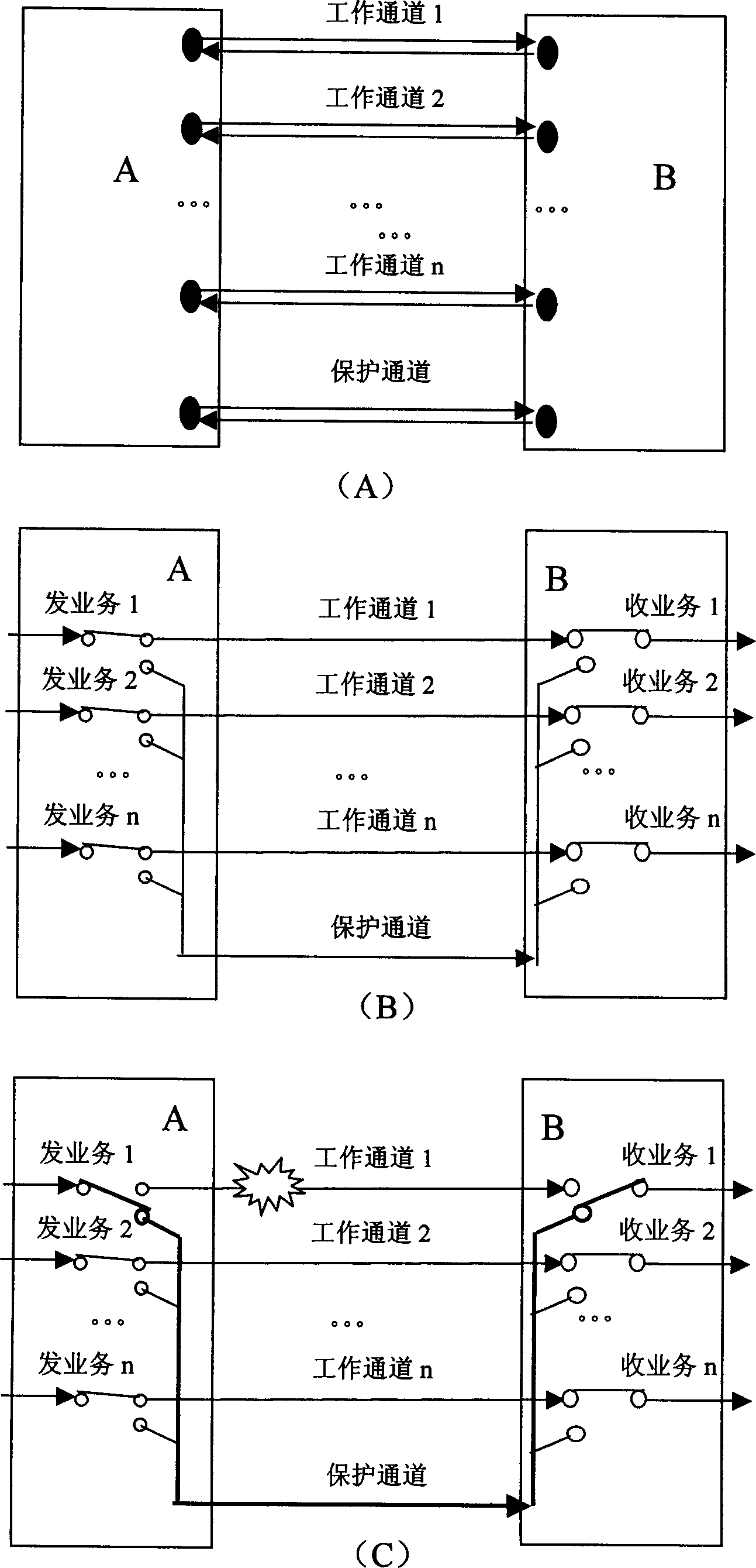
[0037] figure 1 and figure 2 It has already been explained in the background art section.
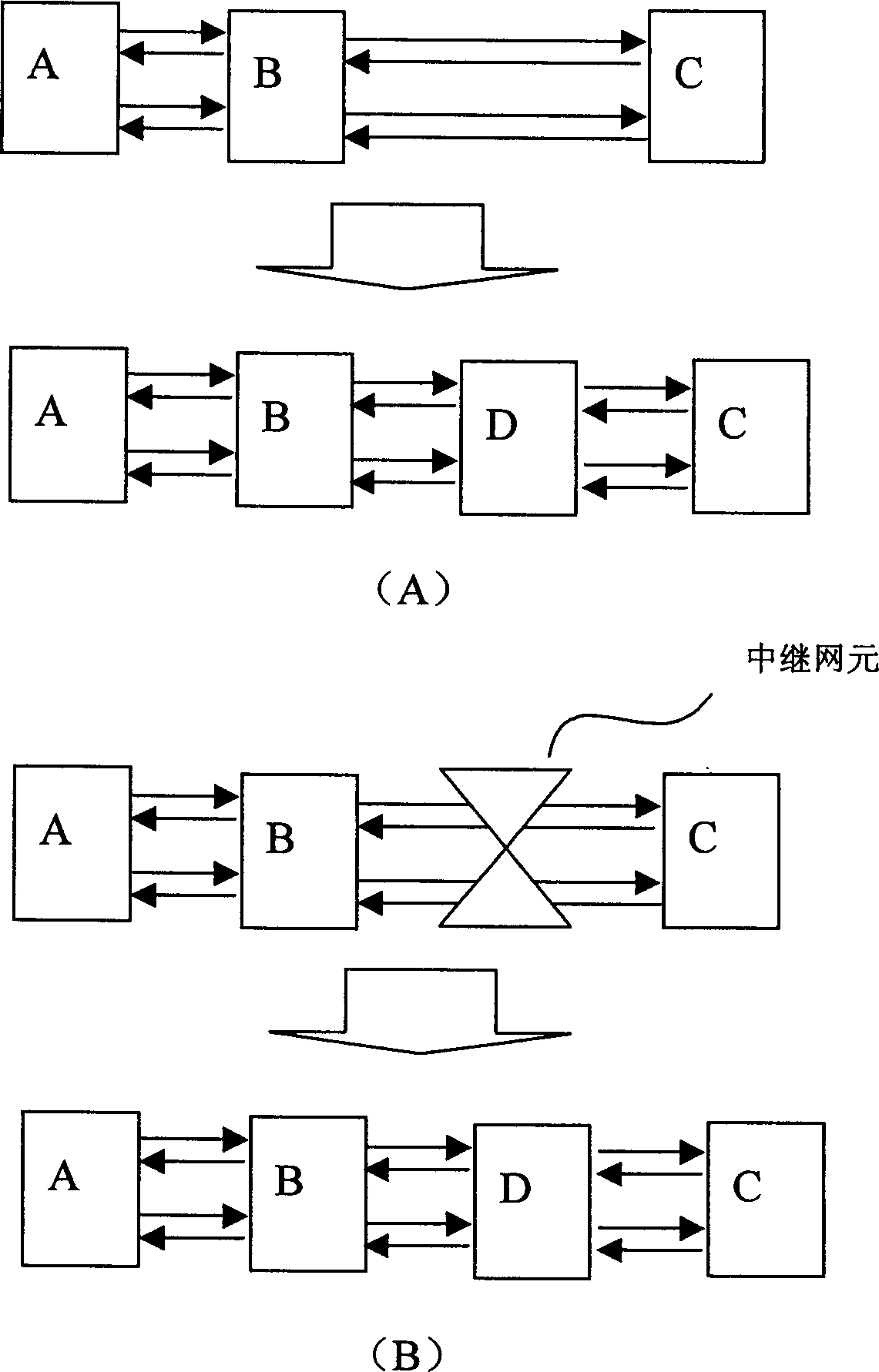
[0038] image 3 It is a schematic diagram of a network element newly added to the network configured as multiplex section link protection. The newly added network element generally includes the following situations: 1) The network element has been running on the network, but it does not belong to the link of the multiplex section, and it is added to the multiplex section by adding a single board, replacing a single board, or using the original reserved optical port. 2) The network element has been running on the network, but originally belonged to the relay device. 3) Add new equipment. image 3 The network element D in (A) belongs to the situations described in 1) and 3). image 3 (B) belongs to the situation described in 2). The method propose...
PUM
 Abstract
Description
Claims
Application Information