Method of image stability improvement for video camera and assistor thereof

A technology of image stabilization and auxiliary devices, applied in image enhancement, image communication, image data processing, etc., can solve the problems of no camera application, unsatisfactory effect, and slow progress, so as to improve image clarity, reduce difficulty and Complexity, effect of reducing harmonic content

Inactive Publication Date: 2005-01-26
SOUTHEAST UNIV
View PDF0 Cites 43 Cited by
  • Summary
  • Abstract
  • Description
  • Claims
  • Application Information

AI Technical Summary

Problems solved by technology

Because of this, although some people try to develop this kind of image stabilization post-processing software, the progress is slow, the effect is not ideal, and there is no application in the camera.

Method used


Image

  • Method of image stability improvement for video camera and assistor thereof
  • Method of image stability improvement for video camera and assistor thereof
  • Method of image stability improvement for video camera and assistor thereof

Examples


Embodiment Construction

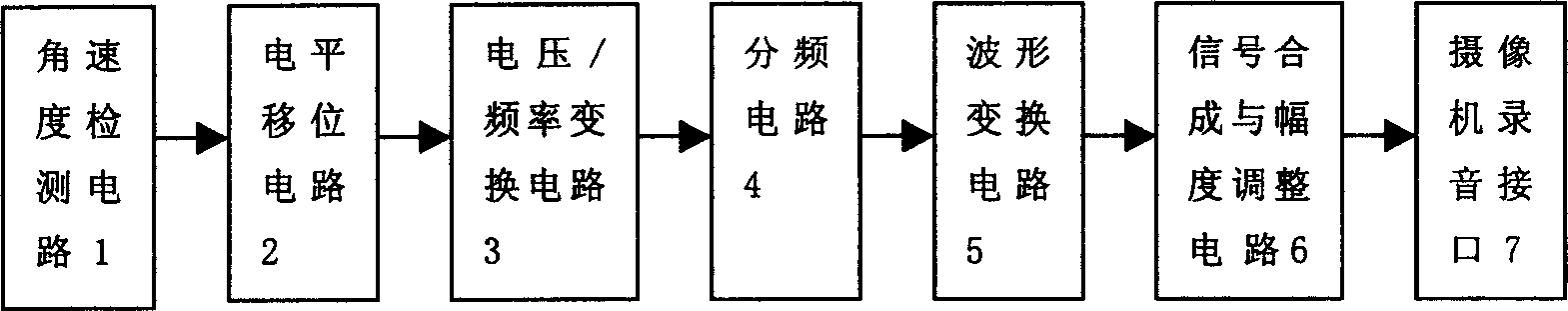
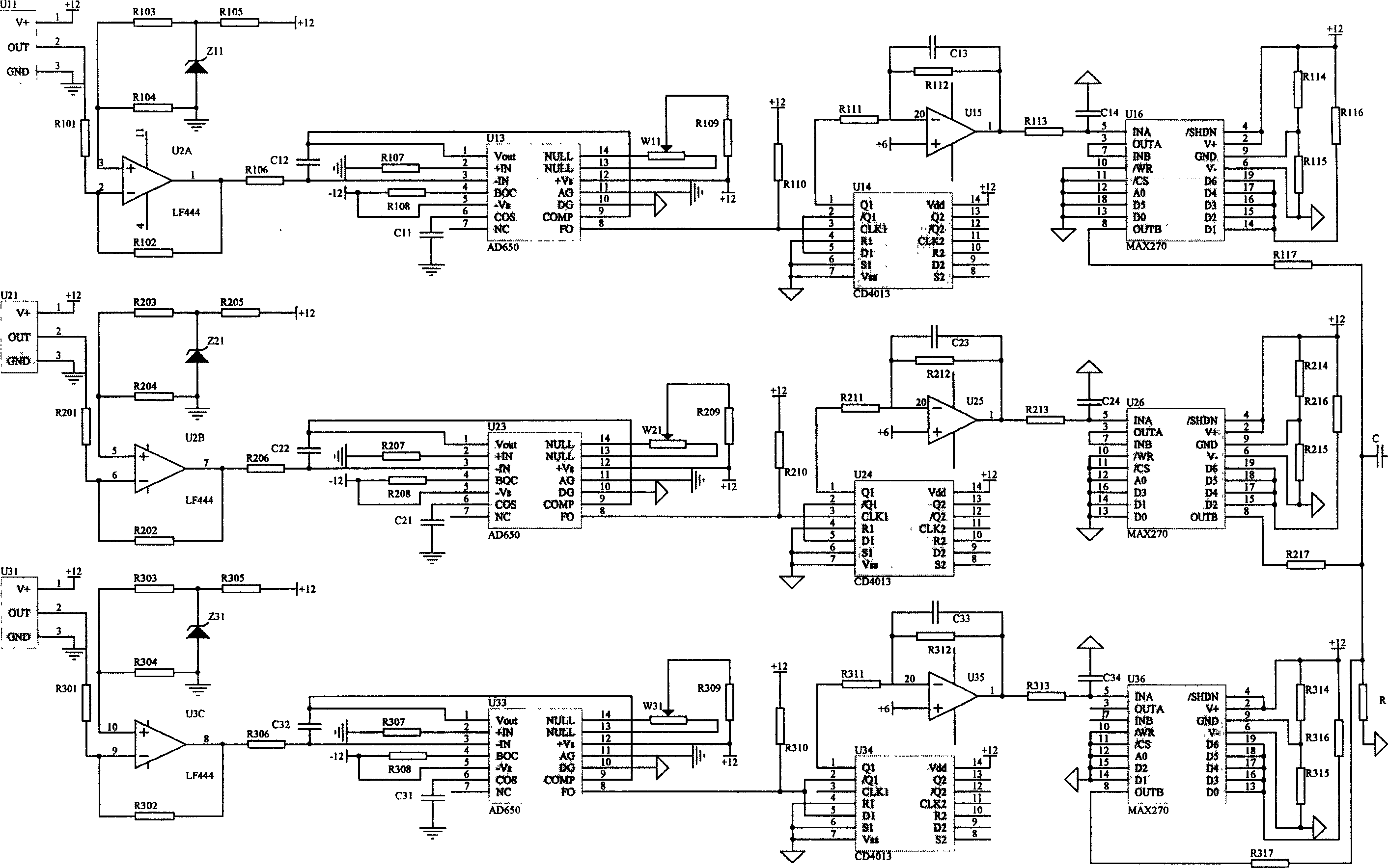
[0026] figure 2 It is the principle circuit diagram of the camera image stabilization auxiliary device of the present invention, and each component can be realized by taking the following models:

[0027] Angular velocity sensor: U11, U21, U31: GYROCHIPII-QRS14;

[0028] Operational amplifiers: U2: A, U2: B, U2: C: LF444;

[0029] Voltage → frequency converter: U13, U23, U33: AD650;

[0030] D flip-flop: U14, U24, U34: CD4013;

[0031] Operational amplifiers: U15, U25, U35: components within U16, U26, U36;

[0032] Biquad low-pass filter; U16, U26, U36: MAX273;

[0033] Zener diodes: Z11, Z21, Z31: 2DW232;

[0034] The working principle of the device is described in detail below.

[0035] First define the coordinate axes and angular motion of the camera. The OX axis is along the camera direction, so the OX axis is perpendicular to the imaging plane of the camera; the OY axis points horizontally to the left of the camera in the imaging plane; the OZ axis points to the z...


PUM


Abstract

The invention relates to an auto-stability method for camera image and the auxiliary device used in hand held state or motion state. It uses angular velocity sensor to check the angular velocity of the camera rotating round the three space axes in real-time and records synchronistical with image signal. The variance of the attitude angle between two pictures would be gained by integral in afterward process software, and the attitude angle variance related to slow-varying low frequency element in motion angular velocity is reserved, meanwhile the attitude angle variance related to dithering angle element would be eliminated. Then, the image dithering would be eliminated by translation and rotation the image. The device is made up of three same circuits. And every process circuit is connected by angular velocity checking circuit which is belonged to signal collection circuit, power lever shifting circuit which is belonged to signal process circuit, voltage/frequency transformation circuit, frequency division circuit, wave transformation circuit, signal compound and extent regulation circuit in series. The output signal is sent to the interface of camera.

Description

technical field [0001] The invention relates to a method and a device for reducing the influence of body shake on image quality when using a camera in a hand-held and moving state, and belongs to the technical field of design and manufacture of camera auxiliary devices. Background technique [0002] With the high development of science and technology and the continuous improvement of people's living standards, cameras are increasingly widely used in the fields of family, industry, and military. However, when used in a hand-held or moving state, the shaking of the camera body leads to shaking or blurring of the image, which seriously affects the visual effect and the recognition, processing and utilization of the image. [0003] From the perspective of kinematics, camera shake can be decomposed into translation shake along the three axes of space and corner shake around the three axes of space. Since the impact of translation shake on the image has ...

Claims


Application Information

Patent Timeline
Patent Type & Authority Applications(China)
IPC IPC(8): G06T5/00H04N5/225
Inventor 李宏生
Owner SOUTHEAST UNIV
Why Eureka
Try Eureka