Continuous centrifuge

A technology of centrifuge and centrifugal turning blue, which is applied in the direction of centrifuge, centrifuge with rotating drum, separation of sugar crystals, etc., and can solve the problem of high power consumption

Inactive Publication Date: 2005-01-26
WDT ENGINEERS PTY LTD
View PDF0 Cites 8 Cited by
  • Summary
  • Abstract
  • Description
  • Claims
  • Application Information

AI Technical Summary

Problems solved by technology

[0011] The power consumption of existing continuous centrifuges is still high, because the rotor must rotate at a very high speed, such as 700-2000rpm, to produce the above-mentioned extremely high acceleration

Method used


Image

  • Continuous centrifuge
  • Continuous centrifuge
  • Continuous centrifuge

Examples


Embodiment Construction

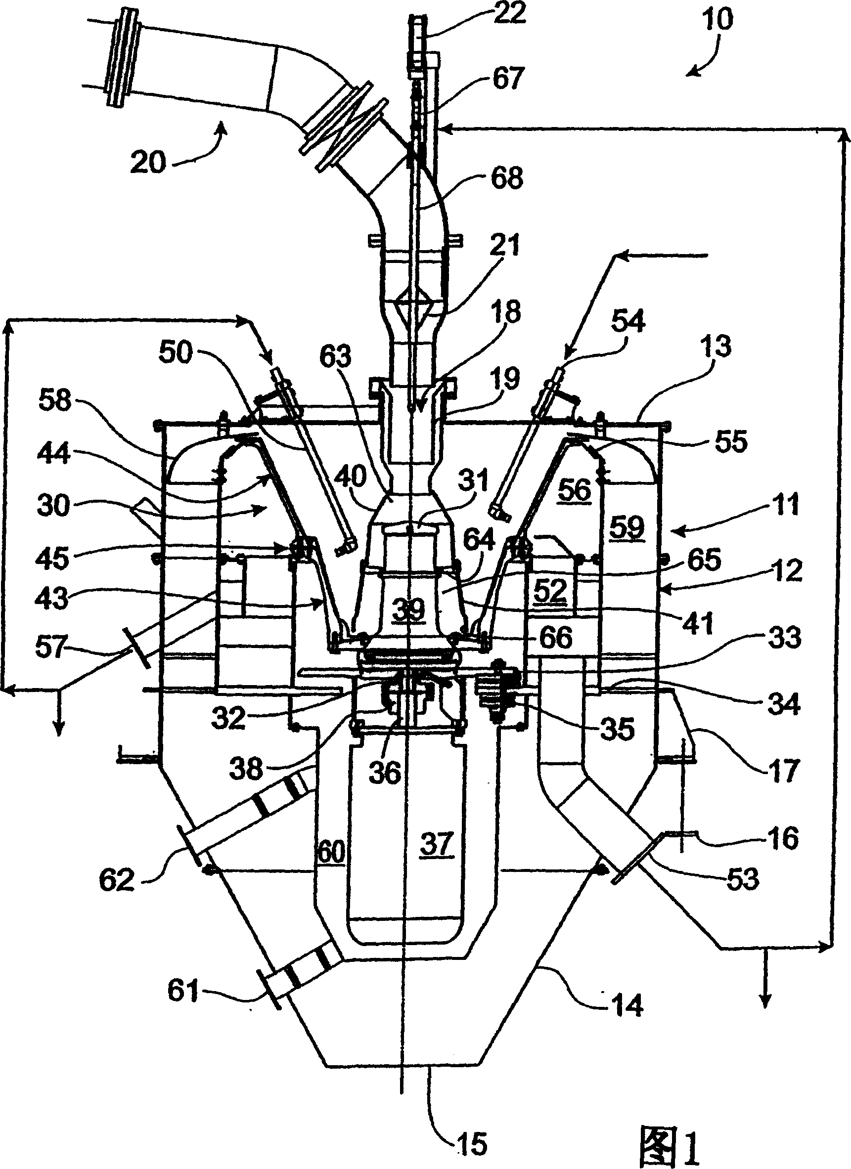
[0046] Referring to Fig. 1, the continuous centrifuge 10 has a housing 11, a detachable top wall 13 and a conical bottom wall 14, wherein the housing 11 has a substantially barrel-shaped side wall 12, the bottom wall 14 With a sugar crystal discharge port 15 . Housing 11 is mounted on a suitable structure 16 via brackets 17 .

[0047] The center of the top wall 13 has a juice inlet 18 which is heated by a steam jacket 19 to control the temperature and viscosity of the juice sent to the centrifuge 10 .

[0048] The juice feed pipe 20 has a flow control valve 21 which is controlled by a pneumatic spool 22 to control the flow of juice to the centrifuge 10 . A flow sensor (not shown) may be connected to the pneumatic spool 22 to measure the power demand of the drive motor to increase juice flow as the flow rate decreases.

[0049] A centrifugal rotor 30, which will be described in more detail below, is mounted rotatably in the center of the housing 11 around a rotary support 31 ...


PUM


Abstract

A continuous centrifuge (10) has a basket (30) with upper and lower basket portions (43, 44) separated by an intermediate slip portion (45). The lower basket portion (43) has an included angle of 40-50 DEG , to separate 'green' molasses from the sugar crystals, while the upper basket portion (44) has an included angle of 50-60 DEG , to separate washed molasses from the sugar crystals. The inner faces of the walls of the basket portions (43, 44) have radial drainage grooves (46), closed at their lower ends and open at their upper ends, to discharge the molasses.

Description

technical field [0001] The invention relates to a continuous centrifuge. [0002] The invention also relates to a rotor for a centrifuge. [0003] In particular, but not exclusively, the present invention relates to a continuous centrifuge (and centrifuge) for separating sugar crystals from viscous substances such as molasses or sugar juice during the processing of the centrifuge during the production of sugar crystals. seperate. [0004] Throughout, the term "centrifuge" shall include "centrifuge machine" as well as "centrifuge bed". Background technique [0005] In recent years, continuous centrifuges have begun to gradually replace batch centrifuges. One reason for this is that the electrical power required by continuous centrifuges is more average than the "peak" power consumption of batch centrifuges. This results in lower costs and operating costs for power supply and transmission equipment. [0006] The purge of sugar juice in the centrifuge consists of two separ...

Claims


Application Information

Patent Timeline
Patent Type & Authority Applications(China)
IPC IPC(8): B04B1/00B04B3/00B04B7/08B04B7/18B04B11/06C13B30/06C13B30/10
CPCB04B3/00B04B11/06C13B30/10C13B30/06B04B7/18
Inventor G·F·伊斯托菲
Owner WDT ENGINEERS PTY LTD
Why Eureka
Try Eureka