Liquid injection system with cylinder flange of liquid syringe

An injection system and liquid technology, applied in the directions of syringes, hypodermic injection devices, infusion sets, etc., to achieve the effect of reliable clamping

Inactive Publication Date: 2005-02-02
NEMOTO KYORINDO KK
View PDF2 Cites 18 Cited by
  • Summary
  • Abstract
  • Description
  • Claims
  • Application Information

AI Technical Summary

Problems solved by technology

[0015] However, even the provided liquid injection device fails to reliably hold the liquid syringe because the barrel adapter only holds the corresponding liquid syringe by placing it in the groove located in the barrel adapter

Method used


Image

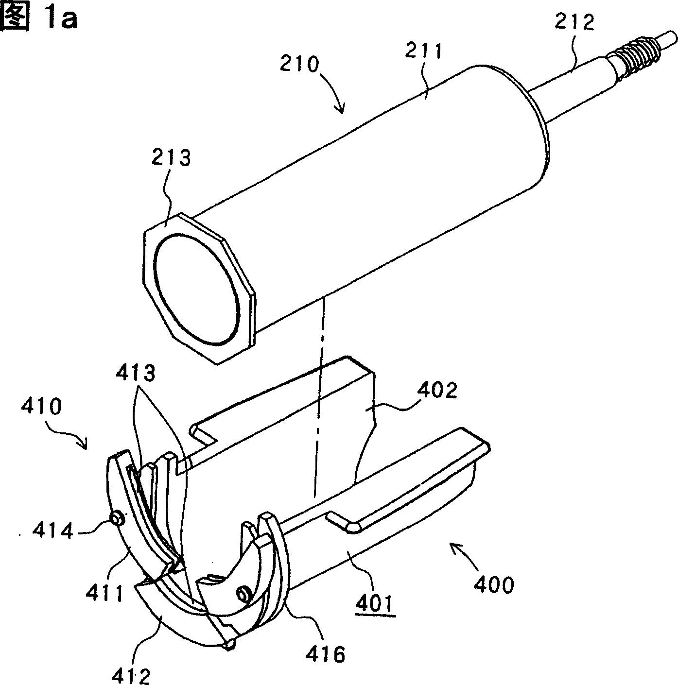
  • Liquid injection system with cylinder flange of liquid syringe
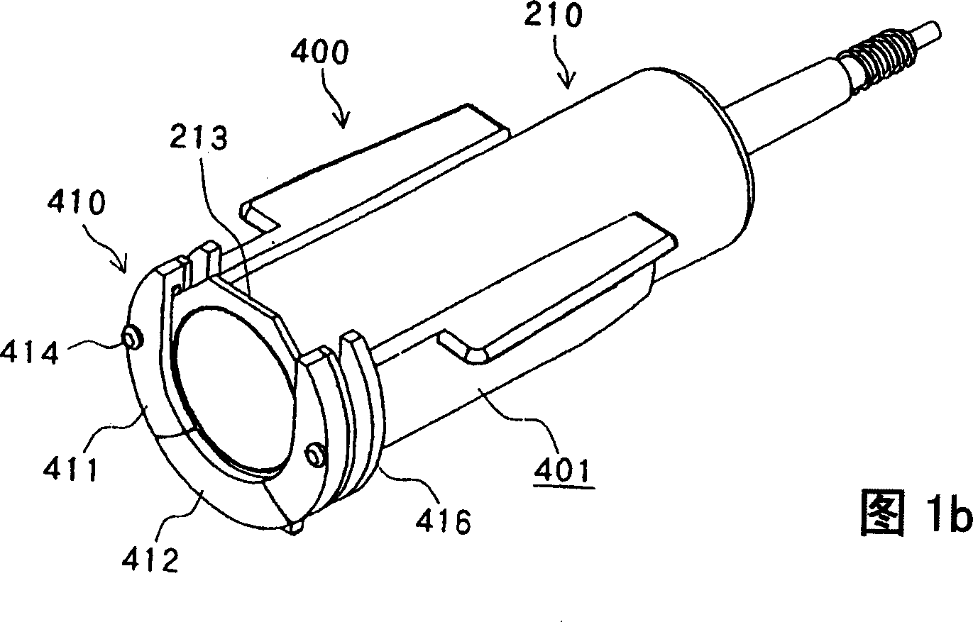
  • Liquid injection system with cylinder flange of liquid syringe
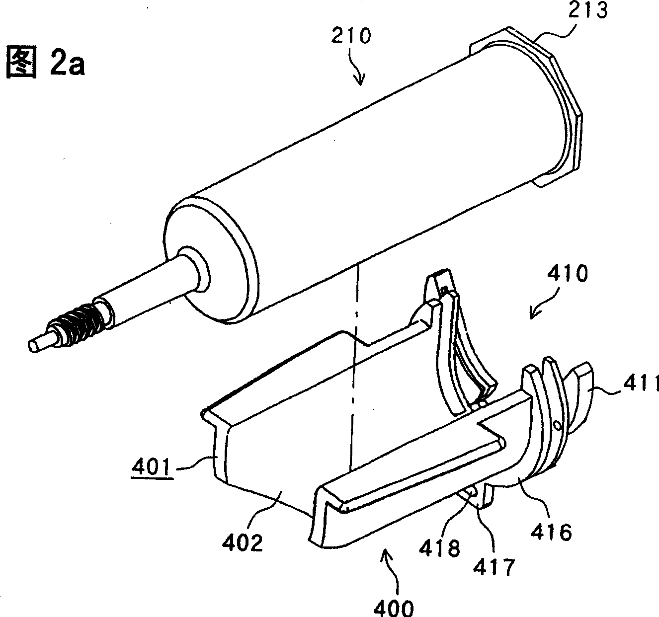
  • Liquid injection system with cylinder flange of liquid syringe

Examples


Embodiment Construction

[0030] The liquid injection system of the present invention will be described below with reference to the accompanying drawings. Structure of the liquid injection system:

[0031] As shown in FIGS. 3 to 5 , a liquid injection system 1000 of the present invention has a liquid injection device 100 , a liquid injector 200 , an MRI device 300 as an imaging diagnostic device, and a cylinder adapter 400 . When a fluorescent image of a patient (not shown) is captured by the MRI apparatus 300 , the liquid injection device 100 injects a liquid such as a contrast medium or a saline solution from the liquid injector 200 into the patient.

[0032] Such as Figure 5 As shown, the MRI apparatus 300 includes an imaging unit 301 as an image capturing mechanism and a control unit 302 connected to each other through a wired communication network (not shown). The imaging unit 301 captures tomographic images of a patient, and the control unit 302 controls operations of the imaging unit 301 .

...


PUM


Abstract

A cylinder adapter (400) holds a cylinder flange (213) of a liquid syringe (200) with movable holders (411) that are selectively openable and closable. The cylinder adapter can reliably hold the liquid syringe.

Description

technical field [0001] The present invention relates to a liquid injection system for injecting liquid into a patient through the relative movement of a cylinder and a plunger of a liquid injector mounted on a liquid injector, and more particularly relates to a liquid injector system in which the liquid injector passes through a cylinder The cartridge adapter is mounted on the liquid injection device. Background technique [0002] Currently, diagnostic imaging equipment used to capture fluorescent images of patients includes CT (Computed Tomography) scanners, MRI (Magnetic Resonance Imaging) devices, and PET (Positron Emission Tomography) devices, ultrasonic diagnostic device, angiography device and MRA (MR angiography) device. [0003] When using such imaging diagnostic devices to capture fluoroscopic images of a patient, it is sometimes actually necessary to inject a fluid, such as a contrast agent or saline solution, into the patient. A liquid injection device for autom...

Claims


Application Information

Patent Timeline
Patent Type & Authority Applications(China)
IPC IPC(8): A61M5/00A61M5/145
CPCA61M5/14546A61M5/1456Y10S128/01A61M5/007
Inventor 根本茂田野敦久
Owner NEMOTO KYORINDO KK
Why Eureka
Try Eureka