
Method of manufacturing ink jet head

A manufacturing method and technology of an inkjet head, which can be applied to inking devices, printing, etc., can solve the problems of high manufacturing cost, poor utilization of raw materials, large equipment, etc., and achieve uniform piezoelectric characteristics and film thickness, etc. Rate improvement, film crack prevention effect

Inactive Publication Date: 2005-02-09
PANASONIC CORP
View PDF1 Cites 1 Cited by
  • Summary
  • Abstract
  • Description
  • Claims
  • Application Information

AI Technical Summary

Problems solved by technology

Therefore, in order to produce a single-crystal MgO substrate longer than 210mm, it is necessary to prepare MgO longer than the above-mentioned length, and a very large facility is required.
Also, even if such a single crystal MgO substrate is produced, the cost of the material is very high due to poor utilization of the raw material.
[0005] In addition, in the replica manufacturing method, it is necessary to form a piezoelectric element (such as PZT) on a substrate composed of single crystal MgO or the like by sputtering or the like, but in order to form a film of PZT in a large area, it is necessary to big equipment
Moreover, obtaining a seamless film with uniform piezoelectric characteristics and film thickness of the piezoelectric element will lead to poor utilization of raw materials.
Therefore, the manufacturing cost becomes very high
[0006] For the above-mentioned reasons, in the conventional linear inkjet head, it is difficult to use the duplication method in terms of quality and cost.

Method used


Image

  • Method of manufacturing ink jet head
  • Method of manufacturing ink jet head
  • Method of manufacturing ink jet head

Examples


Embodiment 1

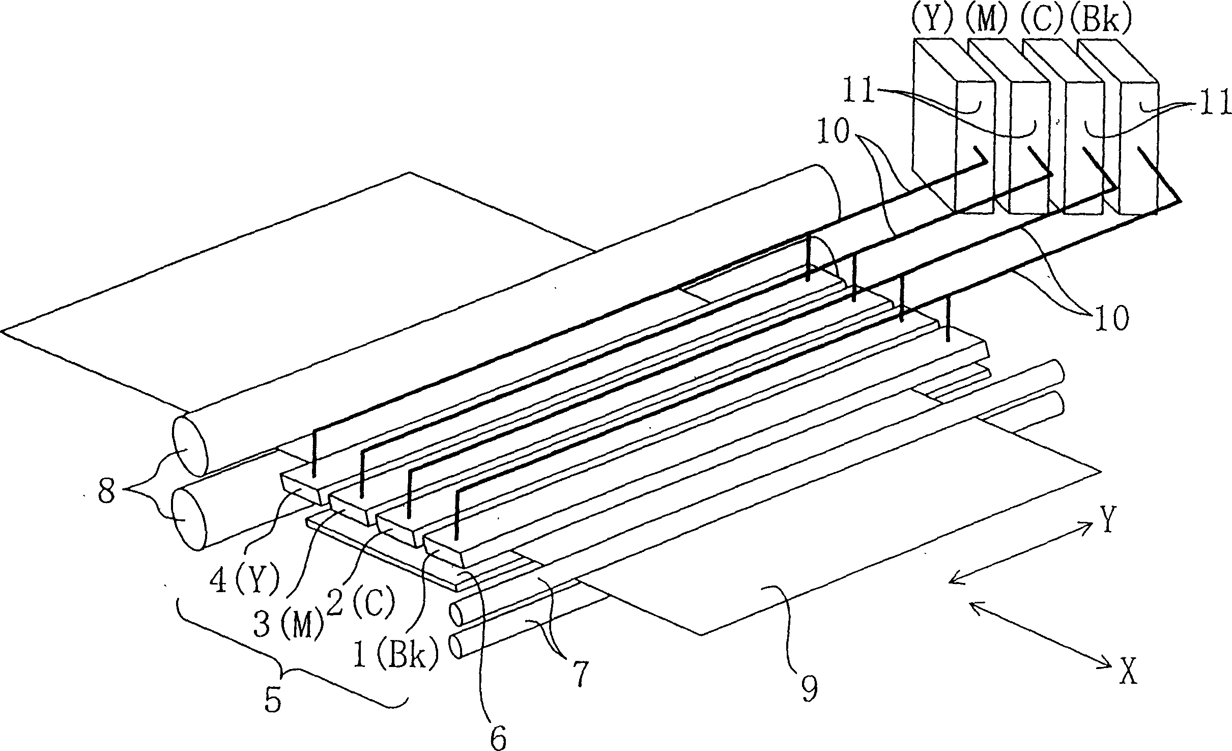
[0084] figure 1 It is a schematic perspective view of an inkjet recording device equipped with a plurality of independent linear inkjet heads independently formed for each color of ink. 1 is the first line inkjet head that ejects black ink (Bk), 2 is the second line inkjet head that ejects cyan ink (C), and 3 is the third line inkjet that ejects magenta ink (M). The line type inkjet head 4 is the 4th line type inkjet head which ejects yellow ink (Y). The inkjet line head 5 combines the first to fourth inkjet line heads 1 to 4 described above, and is configured to sequentially eject black, cyan, magenta, and yellow inks. The inks of the respective colors are supplied to the respective line inkjet heads 1 to 4 through the respective ink tubes 10 connected to the ink tanks 11 .

[0085] The recording medium 9 is transported in a transport direction X perpendicular to the width direction Y of the inkjet head by means of transport rollers 8 . This transport direction X coincides...

Embodiment 2

[0116] The flow path plate 38 and the nozzle plate 36 of Embodiment 1 are each made of a single plate member, but in this embodiment, as Figure 11A or Figure 11B As shown, the flow path plate 38 or the nozzle plate 36 is made of a plurality of plate members.

[0117] Refer below Figure 11A A linear inkjet head including a plurality of nozzle plates 36 will be described. The fabrication method up to bonding of the actuator block 40, the pressure chamber plate 21, and the flow channel plate 38 is the same as that of the first embodiment. The difference from the first embodiment is that a plurality of nozzle plates 36 smaller in area than the pressure chamber plate 21 are bonded to the flow path plate 38 . When bonding, first, each nozzle plate 36 is aligned with the alignment mechanism 23 provided on the pressure chamber plate 21 or the flow path plate 38 , and then each nozzle plate 36 is bonded on the flow path plate 38 .

[0118] Next, refer to Figure 11B A linear in...

Embodiment 3

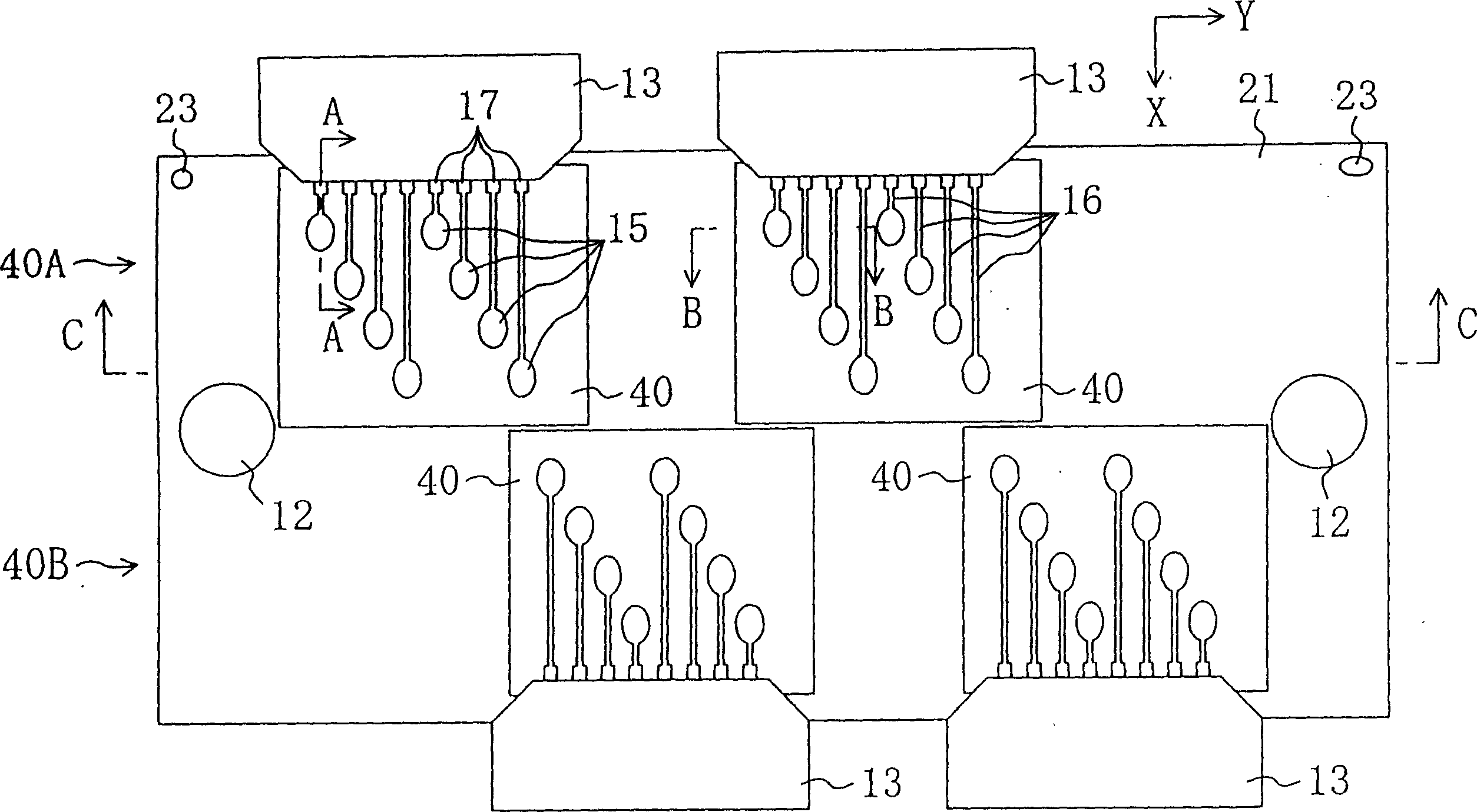
[0121] In each line type inkjet head 5 of embodiment 1 and 2, in the width direction Y of the inkjet head, under the situation that alignment is carried out so that the falling point position of each color ink is the same, the line type inkjet that is independently arranged for each color The heads (1st-4th line type heads 1-4) are mounted on the recording device. On the other hand, in this embodiment, as shown in FIG. 13 , the inkjet line heads of the respective colors are integrated to form a single inkjet line head 5 . Pressure chambers 22 for inks of each color are arranged on the pressure chamber plate 21 , and the inks of each color are supplied to individual line inkjet heads 5 through ink tubes 10 .

[0122] Figure 14 It is a partial top view of the pressure chamber plate 21 related to this embodiment. On the pressure chamber plate 21, the pressure chambers 22 and the common liquid chamber 18 for each color ink of black (Bk), cyan (C), magenta (M) and yellow (Y) are...


PUM


Abstract

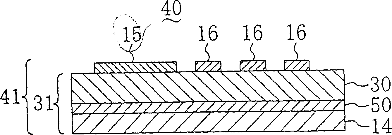
The invention relates to a manufacturing method for a linear ink jet head, comprising a block manufacturing working procedure which stacks at least a first electrode, piezoelectric element and a second electrode or at least the first electrode, piezoelectric element, the second electrode and the vibration board in sequence on a plurality of substrates with smaller area than that of the pressure chamber board to manufacture a plurality of actuator blocks, a first bonding working procedure which bonds the actuator blocks on the substrates onto one side of the pressure chamber board so that a plurality of pressure chambers arranged on the pressure chamber board can be covered by the second electrode of the actuator blocks or the vibration board, a working procedure of removing the substrates and a working procedure of forming the pattern of the first electrode of each actuator blocks.

Description

technical field [0001] The invention relates to a method for manufacturing a linear inkjet head. Background technique [0002] In recent years, ink-jet heads having nozzles arranged at a high density as disclosed in Japanese Laid-Open Patent Publication No. Hei 10-286953 and manufactured by a so-called duplication method have been widely known. The replica manufacturing method is a very good manufacturing method as a method of manufacturing a high-density print head. In the replica manufacturing method, first, a thin film actuator is manufactured as follows, for example. Specifically, individual electrodes are formed on a substrate composed of single crystal MgO or the like, and then a perovskite-type dielectric thin film composed of PZT is formed on the individual electrodes as a piezoelectric body. Then, a vibrating plate serving also as a common electrode is formed on the piezoelectric body by sputtering or the like. Then, the actuator thus produced is bonded to the pr...

Claims


Application Information

Patent Timeline
Patent Type & Authority Applications(China)
IPC IPC(8): B41J2/01B41J2/045B41J2/055B41J2/14B41J2/16
CPCB41J2/161B41J2/1646B41J2202/20B41J2/1629B41J2/14233
Inventor 松尾浩之池田浩二曾我美淳立川雅一郎
Owner PANASONIC CORP
Learn More