Ink nozzle and making method and ink jet type recorder
A technology of inkjet head and ink, which is applied in the field of inkjet head and inkjet recording device, and can solve the problems of large equipment, poor utilization rate of raw materials, high material cost, etc.
- Summary
- Abstract
- Description
- Claims
- Application Information
AI Technical Summary
Problems solved by technology
Method used
Image
Examples
Embodiment 1
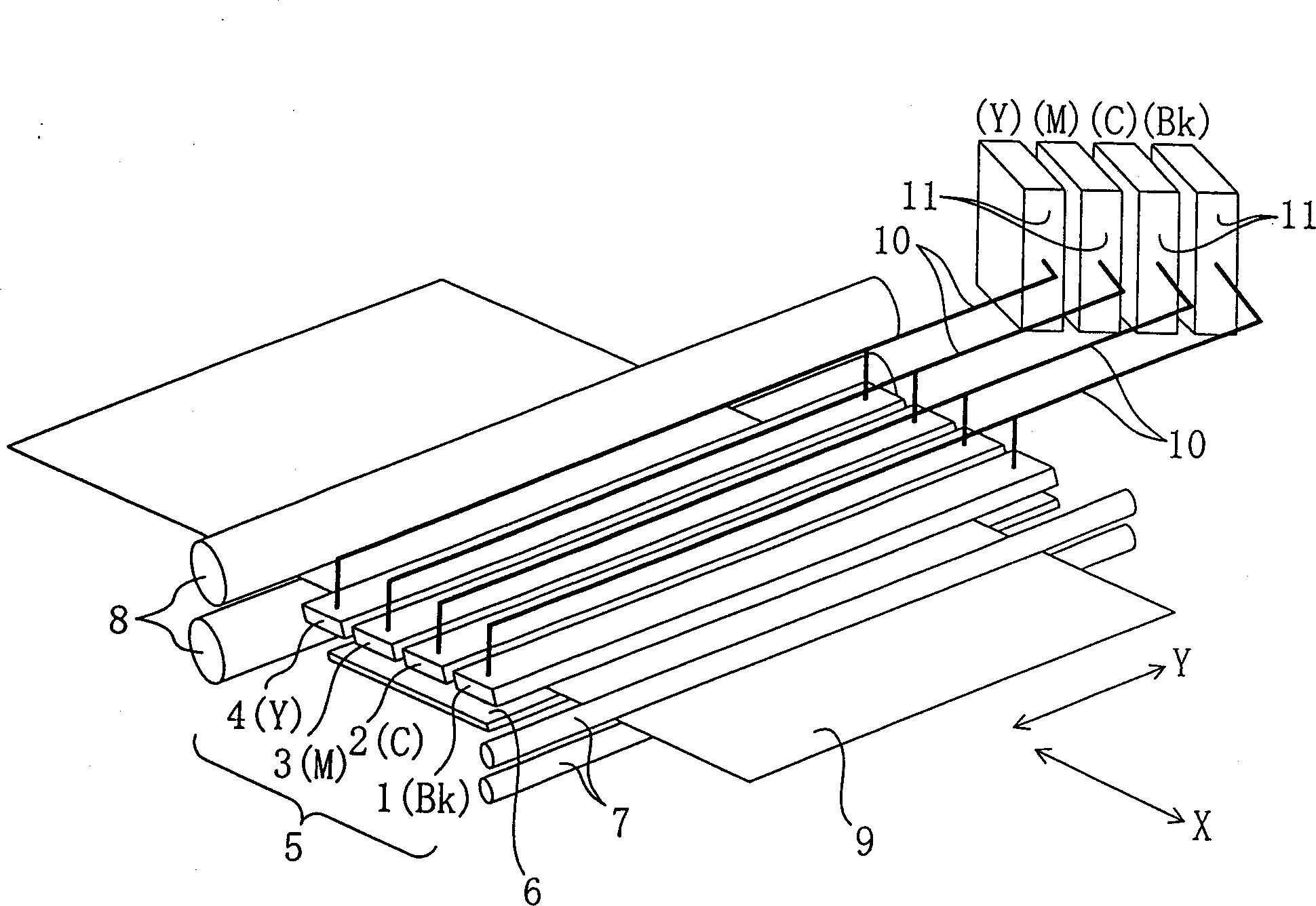
[0096] figure 1 It is a schematic perspective view of an inkjet recording device equipped with a plurality of independent linear inkjet heads independently formed for each color of ink. 1 is the first line inkjet head that ejects black ink (Bk), 2 is the second line inkjet head that ejects cyan ink (C), and 3 is the third line inkjet that ejects magenta ink (M). The line type inkjet head 4 is the 4th line type inkjet head which ejects yellow ink (Y). The inkjet line head 5 combines the first to fourth inkjet line heads 1 to 4 described above, and is configured to sequentially eject black, cyan, magenta, and yellow inks. The inks of the respective colors are supplied to the respective line inkjet heads 1 to 4 through the respective ink tubes 10 connected to the ink tanks 11 .
[0097] The recording medium 9 is transported in a transport direction X perpendicular to the width direction Y of the inkjet head by means of transport rollers 8 . This transport direction X coincides...
Embodiment 2
[0128] The flow path plate 38 and the nozzle plate 36 of Embodiment 1 are each made of a single plate member, but in this embodiment, as Figure 11A or Figure 11B As shown, the flow path plate 38 or the nozzle plate 36 is made of a plurality of plate members.
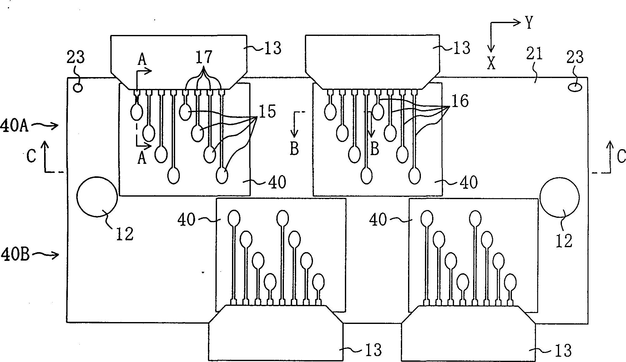
[0129] Refer below Figure 11A A linear inkjet head including a plurality of nozzle plates 36 will be described. The fabrication method up to bonding of the regulator block 40, the pressure chamber plate 21, and the flow path plate 38 is the same as that of the first embodiment. The difference from the first embodiment is that a plurality of nozzle plates 36 smaller in area than the pressure chamber plate 21 are bonded to the flow path plate 38 . When bonding, first, each nozzle plate 36 is aligned with the alignment mechanism 23 provided on the pressure chamber plate 21 or the flow path plate 38 , and then each nozzle plate 36 is bonded on the flow path plate 38 .
[0130] Next, refer to Figure 11B A linear inkj...
Embodiment 3
[0133] In each line type inkjet head 5 of embodiment 1 and 2, in the width direction Y of the inkjet head, under the situation that alignment is carried out so that the falling point position of each color ink is the same, the line type inkjet that is independently arranged for each color Heads (1st-4th linear nozzles 1-4) are installed on the recording device. On the other hand, in this embodiment, as shown in FIG. 13 , the inkjet line heads of the respective colors are integrated to form a single inkjet line head 5 . Pressure chambers 22 for inks of each color are arranged on the pressure chamber plate 21 , and the inks of each color are supplied to individual line inkjet heads 5 through ink tubes 10 .
[0134] Figure 14 It is a partial top view of the pressure chamber plate 21 related to this embodiment. On the pressure chamber plate 21, the pressure chambers 22 and the common liquid chamber 18 for each color ink of black (Bk), cyan (C), magenta (M) and yellow (Y) are ar...
PUM
| Property | Measurement | Unit |
|---|---|---|
| Thickness | aaaaa | aaaaa |
| Thickness | aaaaa | aaaaa |
Abstract
Description
Claims
Application Information
 - R&D
- Intellectual Property
- Life Sciences
- Materials
- Tech Scout
- Unparalleled Data Quality
- Higher Quality Content
- 60% Fewer Hallucinations
Browse by: Latest US Patents, China's latest patents, Technical Efficacy Thesaurus, Application Domain, Technology Topic, Popular Technical Reports.
© 2025 PatSnap. All rights reserved.Legal|Privacy policy|Modern Slavery Act Transparency Statement|Sitemap|About US| Contact US: help@patsnap.com


