
Vehicle-rollover detecting apparatus and vehicle-rollover detecting method

A technology for identifying devices and vehicles, applied in vehicle components, vehicle safety arrangements, transportation and packaging, etc., can solve problems such as slow time, inability to correctly detect acceleration, and difficulty in connecting

Inactive Publication Date: 2005-02-09
NEXGEN CONTROL SYST LLC
View PDF3 Cites 22 Cited by
  • Summary
  • Abstract
  • Description
  • Claims
  • Application Information

AI Technical Summary

Problems solved by technology

However, the problem with the judgment method described in Patent Document 1 is that, in the case where rollover is eventually caused, when the roll angular velocity is very large or suddenly becomes large, the time for judgment using the ω-θ two-dimensional diagram is slow.
[0006] However, the methods described in the above-mentioned Patent Documents 2 and 3 have the following problem, that is, when the vehicle rolls, the detection axis of the sensor is also inclined, so the magnitude of the acceleration that actually occurs in the lateral direction cannot be accurately detected. Another problem is that When the Y-axis acceleration sensor is used to detect the centrifugal force, and the Z-axis acceleration sensor is used to detect the acceleration of gravity and the acceleration of vertical vibration, since the vehicle tilt acceleration and centrifugal force can be detected in both directions of the Y-axis and Z-axis, it is difficult to separate each The accelerations detected by the sensors are individually linked to the cause of the rollover

Method used


Image

  • Vehicle-rollover detecting apparatus and vehicle-rollover detecting method
  • Vehicle-rollover detecting apparatus and vehicle-rollover detecting method
  • Vehicle-rollover detecting apparatus and vehicle-rollover detecting method

Examples


Embodiment Construction

[0017] One embodiment of the present invention will be described below.

[0018] Embodiment 1

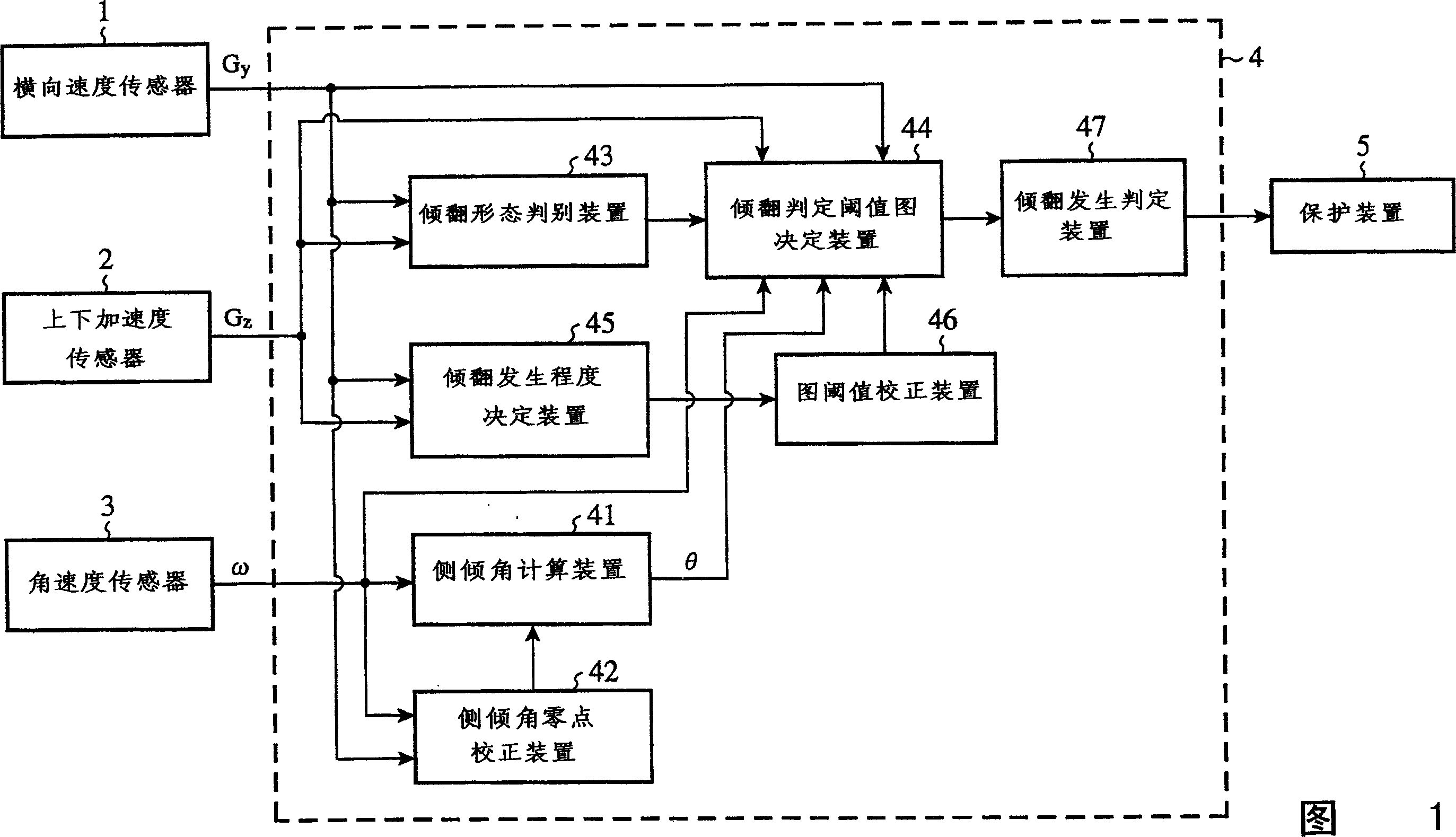
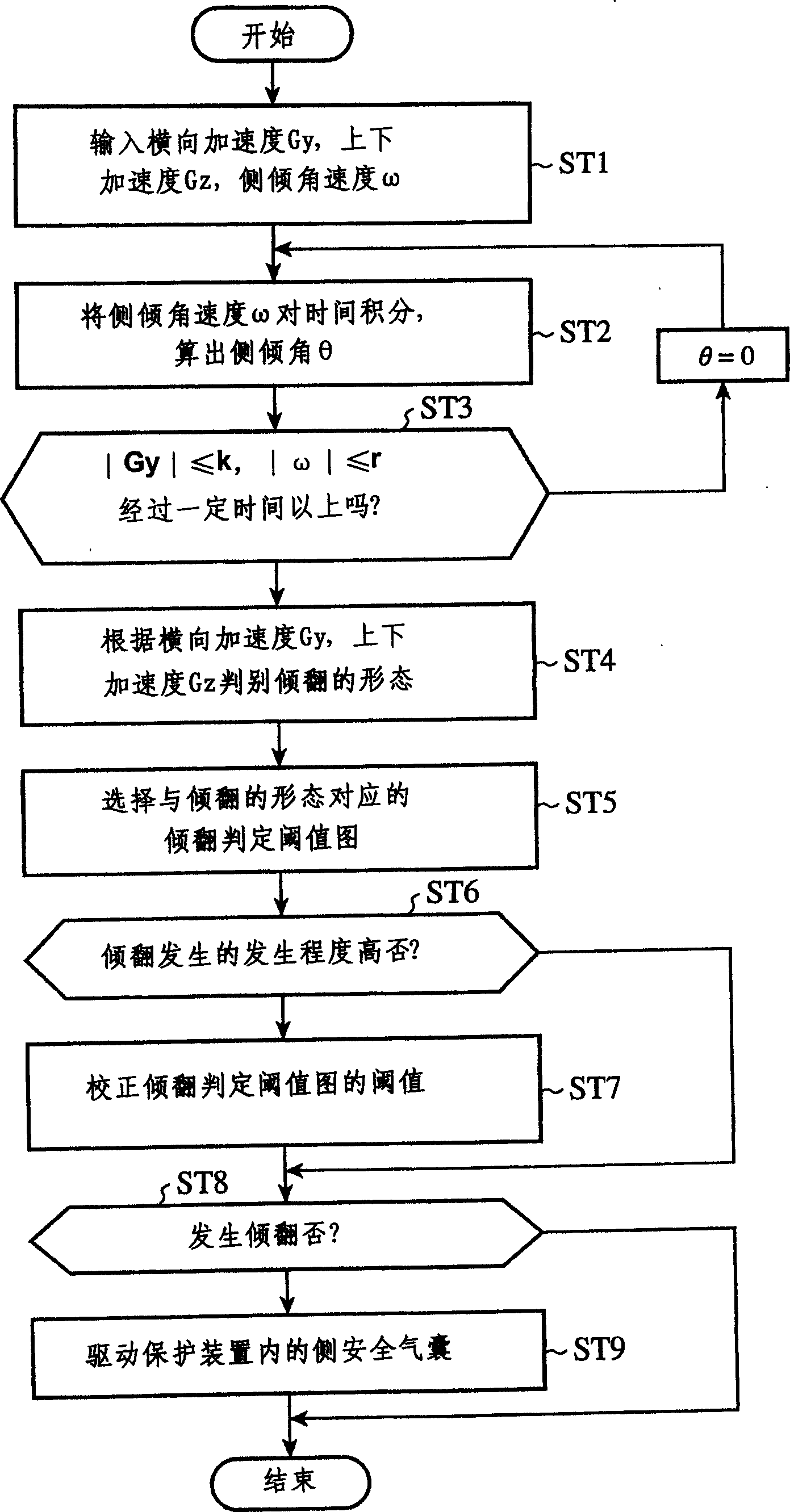
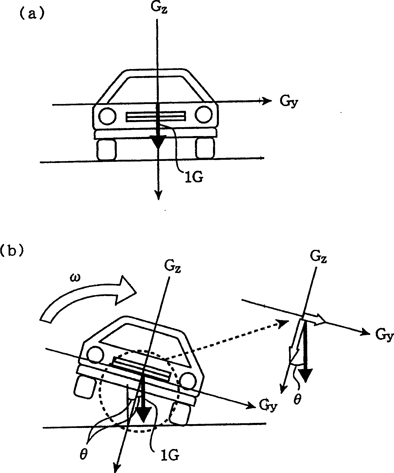
[0019] 1 is a functional block diagram showing a vehicle rollover judging device according to Embodiment 1 of the present invention, figure 2 It is a flow chart for explaining the operation of the vehicle rollover judging device according to Embodiment 1 of the present invention, image 3 For explaining the schematic diagram of the overturning form of Embodiment 1 of the present invention, Fig. 4 is a schematic diagram showing various overturning forms of Embodiment 1 of the present invention, Figure 5 Fig. 6 is a schematic diagram showing a tipping judgment threshold map according to Embodiment 1 of the present invention.

[0020] In Fig. 1, on the input side of the determination device 4, a lateral acceleration sensor 1 as a lateral acceleration detection device that detects the acceleration acting in the lateral direction of the vehicle, that is, a lateral acceleration; The v...


PUM


Abstract

The apparatus for discriminating the roll-over of the vehicle comprises sensors 1, 2 and 3 for detecting the lateral acceleration, the vertical acceleration, and the rolling acceleration of the vehicle, respectively, a means 41 for calculating the rolling angle of the vehicle by integrating the rolling acceleration, a means 42 for carrying out the zero point correction of the rolling angle based on the lateral acceleration and the rolling acceleration, a means 43 for discriminating the pattern of the roll-over based on the resultant acceleration of the lateral acceleration and the vertical acceleration, a means 44 for determining a roll-over discrimination threshold map of the vehicle according to the pattern of the roll-over, a means 45 for determining an occurrence rate of the roll-over based on the resultant acceleration of the lateral acceleration and the vertical acceleration, a means 46 for correcting the threshold value of the roll-over discrimination threshold map based on the occurrence rate, and a means 47 for discriminating the occurrence of the roll-over based on the roll-over discrimination threshold map having the corrected threshold value.

Description

technical field [0001] The invention relates to a vehicle rollover discrimination device and a vehicle rollover discrimination method for detecting vehicle rollover (lateral rollover). Background technique [0002] Conventionally, as the most general method of rollover detection methods, there is a method of determining rollover based on a two-dimensional map of the vehicle's roll angle θ and roll angular velocity ω (for example, refer to Patent Document 1). However, the problem with the judgment method described in Patent Document 1 is that, in the case where rollover is finally caused, when the roll angular velocity is very large or suddenly becomes large, the time for judgment using the ω-θ two-dimensional diagram is slow. . In order to solve this problem, a method has been proposed, which is to classify the form of overturning according to the magnitude of the acceleration detected by the acceleration sensor (Y-axis and / or Z-axis), and adopt the overturning judgment thr...

Claims


Application Information

Patent Timeline
Patent Type & Authority Applications(China)
IPC IPC(8): B60R21/01B60G17/015B60G23/00B60R21/00B60R21/013B60R21/0132B60R21/13B60R21/16B60R21/20
CPCB60T2230/03B60R2021/01325B60G2400/102B60G2800/0124B60G17/015B60G2800/012B60R2021/0018B60G2400/0511B60G2400/104B60G2400/0521B60R21/0132B60R2021/0025B60R2021/0027
Inventor 铃木涼太郎有吉雄二中本昌宏
Owner NEXGEN CONTROL SYST LLC
Learn More