Friction drive conveyor

A technology of friction drive and conveying device, which is applied in the direction of transportation and packaging, conveyors, motor vehicles, etc., and can solve the problems of increasing the number of motors used for driving the friction drive wheel, increasing the cost, delaying the stop period, etc.

Active Publication Date: 2005-02-09
DAIFUKU CO LTD
View PDF1 Cites 16 Cited by
  • Summary
  • Abstract
  • Description
  • Claims
  • Application Information

AI Technical Summary

Problems solved by technology

In this proposal, the stop timing of the friction drive wheel in contact with the side surface of the sharp and narrow end on the rear end side of the load lever is delayed, and the load lever (traveling body for transport) is moved as far as possible by the rotation of the friction drive wheel. It is sent forward and then stopped, but in this scheme, it cannot be guaranteed that the loading lever (transportation travel) can be strongly driven as it is when the friction drive wheel that is in contact with the linear friction surface of the loading lever is driven in rotation. In the case of advancing forward, the cost of adding the timer function cannot be avoided
Obviously, it is also considered that from the beginning, the distance between the friction drive wheels is smaller than the total length of the linear friction surface of the loading rod. However, two or more friction drive wheels must be in contact with one loading rod, and each friction drive The drive control of the wheels is complicated, and the number of friction drive wheels and their driving motors increases, while the cost increases significantly and the practicability decreases.

Method used


Image

  • Friction drive conveyor
  • Friction drive conveyor
  • Friction drive conveyor

Examples


Embodiment Construction

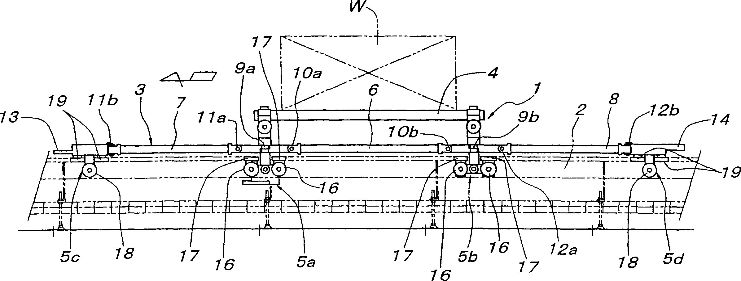
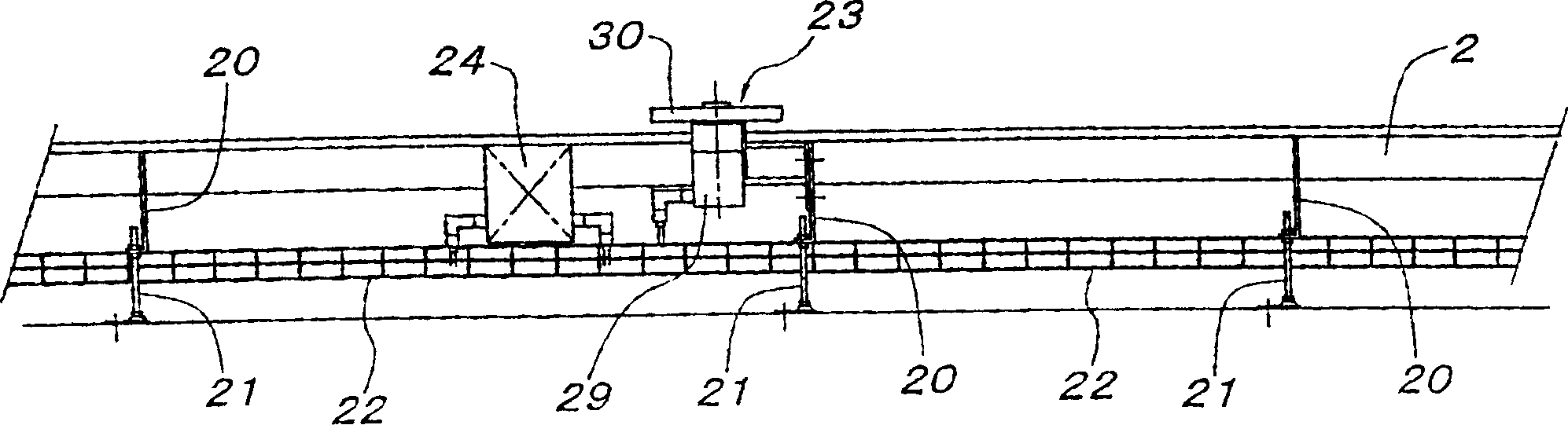
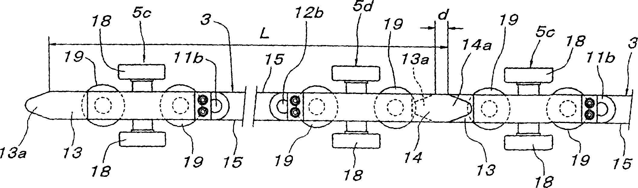
[0052] Below according to accompanying drawing, preferred embodiment of the present invention is described, in Fig. 1~ image 3 Among them, reference numeral 1 denotes a traveling body for transportation of the floor traveling trolley type, and reference numeral 2 denotes a guide rail for supporting and guiding the traveling body 1 for transportation. The running body 1 for transportation includes a loading bar 3 parallel to the traveling direction, a cargo platform 4 that supports the object W to be transported, and four tackles 5 a to 5 a that support and guide the loading bar 3 . 5d.

[0053] The loading bar 3 is composed of a middle loading bar 6 , a front loading bar 7 and a rear loading bar 8 , and the middle loading bar 6 connects two front and rear load blocks 5 a and 5 b in the middle that support the front and rear ends of the cargo platform 4 . , the front side loading bar 7 connects the front end guide block 5c and the front side load block 5a, and the rear side lo...


PUM


Abstract

Each of the friction drive wheels 30 comprises a brake-less motor 29 driving the friction drive wheel and a sensor 32 detecting the state of the contact of the friction surface 15 of the traveling body 1 for carrying on the friction drive wheel 30. The friction drive wheels 30 are disposed in an at least specified district in a carrying route at equal intervals not longer than (same or slightly shorter than) the overall length L of the friction surface 15 of the traveling body 1 for carrying. Based on the detection state of sensors 32, a control means 24 controlling the friction drive wheels 30 is controlled to start the driving of the friction drive wheel 30 in contact with the friction face 15 of the traveling body 1 for carrying when the friction drive wheel 30 on the downstream side is brought in an empty state and stop the driving of the friction drive wheel 30 apart from the friction surface 15 of the traveling body 1 for carrying.

Description

technical field [0001] The invention relates to a friction-driven conveying device. The friction-driven conveying device propels a conveying traveling body capable of traveling along a certain traveling passage through friction driving wheels on the side of the traveling passage. Background technique [0002] As this kind of friction-driven conveying device, for example, the Japanese No. 2003-54731 document (hereinafter referred to as "patent document") as Japanese Patent Laid-Open Document (hereinafter referred to as "patent document") etc. is known to have the following type, wherein, on the traveling body for conveying, A loading lever is provided along the traveling direction, and a driving assembly is provided on the traveling passage side, and the driving assembly has a friction driving wheel which rotates in contact with a friction surface formed on a side surface of the loading lever. [0003] As described in the above-mentioned patent documents, the end of the loadi...

Claims


Application Information

Patent Timeline
Patent Type & Authority Applications(China)
IPC IPC(8): B61B13/12B62D65/18B65G35/06
CPCB61B13/127B62D65/18B65G2203/0283B65G2203/047B65G35/06
Inventor 西原重善村上裕之三好和彦森田进井场敏之小幡纯土
Owner DAIFUKU CO LTD
Why Eureka
Try Eureka