Processing cartridge with power inputting buffer unit

A buffer device and power input technology, which is applied in the field of processing boxes, can solve problems such as easy occurrence of motors and shortened service life

Inactive Publication Date: 2005-02-09
上海阿格感光材料有限公司
View PDF0 Cites 4 Cited by
  • Summary
  • Abstract
  • Description
  • Claims
  • Application Information

AI Technical Summary

Problems solved by technology

[0004] In the above two power transmission methods, at the moment when the drive motor of the electrophotographic image forming equipment starts to work, an impulse with a high amplitude will inevitably be generated between the power output mechanism and the power input mechanism of the process box, which not only makes the output mechanism Both the input mechanism and the input mechanism will have a shortened service life due to this repeated overload, and the motor is also prone to problems

Method used


Image

  • Processing cartridge with power inputting buffer unit
  • Processing cartridge with power inputting buffer unit
  • Processing cartridge with power inputting buffer unit

Examples


Embodiment Construction

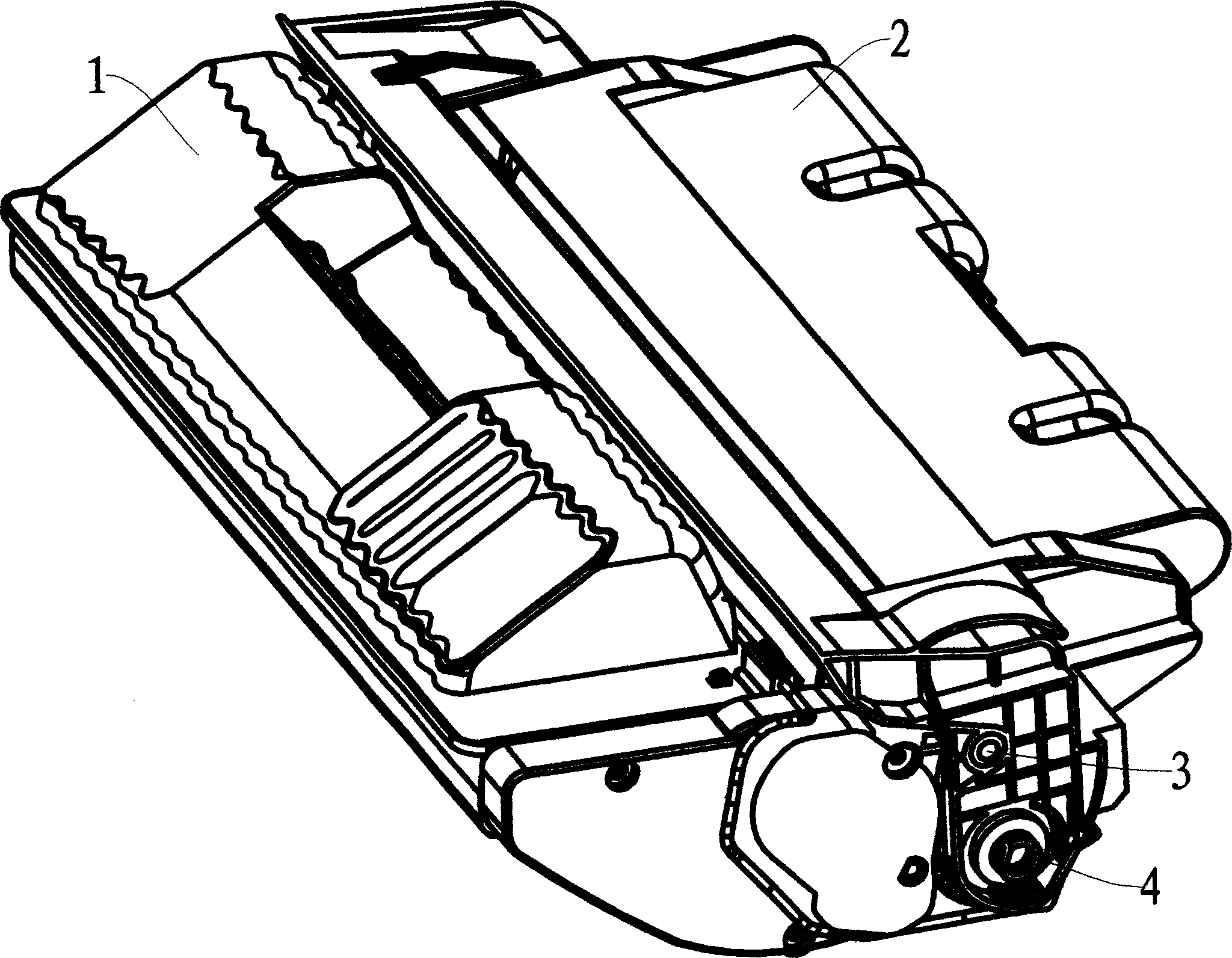
[0032] see figure 1 , the processing box is composed of a toner bin 1 and a waste toner bin 2, the toner bin 1 and the waste toner bin 2 are rotatably connected within a small angle range through a pair of hinges 3 arranged on the side walls of the two bins, figure 1 Only one hinge 3 can be seen in the figure, the other hinge is on the opposite invisible surface. At the shaft end of the photosensitive drum protruding from the side of the process cartridge, an axially protruding elastic torque receiving member is fixed, in this example, a torsion spring 4, when the process cartridge is placed in the electrophotographic image forming apparatus When it is used, it can cooperate with the power output end of the electrophotography image forming equipment to input the power of the moving parts of the process box such as the photosensitive drum, the stirring frame, the magnetic roller, and the charging roller.

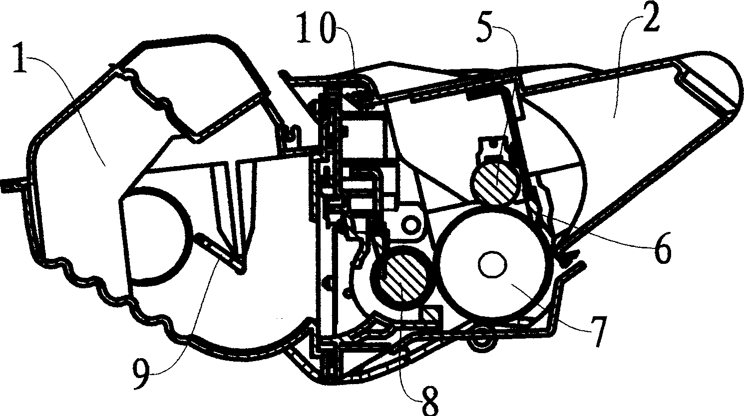
[0033] see figure 2 , the processing box that the present invention p...


PUM


Abstract

The treating box with power input buffer includes one powder bin with carbon powder, carbon powder stirrer and magnetic roller in the power outlet; waste powder bin supporting one rotatable photosensitive drum for receiving light signal to generate latent image; one charge roller to charge the photosensitive drum; and one cleaning scraper to eliminate the residual carbon powder on the surface of the photosensitive drum. The powder bin and the waste powder bin are hinged, the stirrer and the magnetic roller accept the driving force from the photosensitive drum via gear line, and the photosensitive drum has one elastic torque accepting part in its one end. In the time the treating box is started to generate maximum instant impulse, the elastic torque accepting part will deform to remit the impact.

Description

technical field [0001] The present invention relates to a process cartridge used in an electrophotographic image forming apparatus, particularly a process cartridge having a power input buffer. Background technique [0002] Electrophotographic image forming equipment such as copiers, fax machines, laser printers, etc., usually use a detachable process box as a container for replenishing toner and cooperate with it to form images on the medium. The power source of the moving parts in the process box is As for the motor in the electrophotographic image forming equipment, the output end of the power output mechanism of the motor can be a gear, or a concave hole with a non-circular section. At present, the power input mechanisms corresponding to the above power output modes of the processing box respectively include two types of gear meshing and protrusions cooperating with non-circular cross-section concave holes. [0003] The defect of the gear meshing transmission method is ...

Claims


Application Information

Patent Timeline
Patent Type & Authority Applications(China)
IPC IPC(8): G03G21/18
Inventor 李军
Owner 上海阿格感光材料有限公司
Why Eureka
Try Eureka