

Pwm switching regulator control circuit
A switching voltage regulator and control circuit technology, applied in circuit devices, control/regulation systems, emergency protection circuit devices, etc., can solve the problems of increasing ripple voltage and reducing output voltage, so as to prevent output voltage drop, ripple The effect of small wave voltage
- Summary
- Abstract
- Description
- Claims
- Application Information
AI Technical Summary
Problems solved by technology
Method used
Image

Examples
Embodiment Construction
[0019] Hereinafter, preferred embodiments of the present invention will be described in detail with reference to the accompanying drawings.
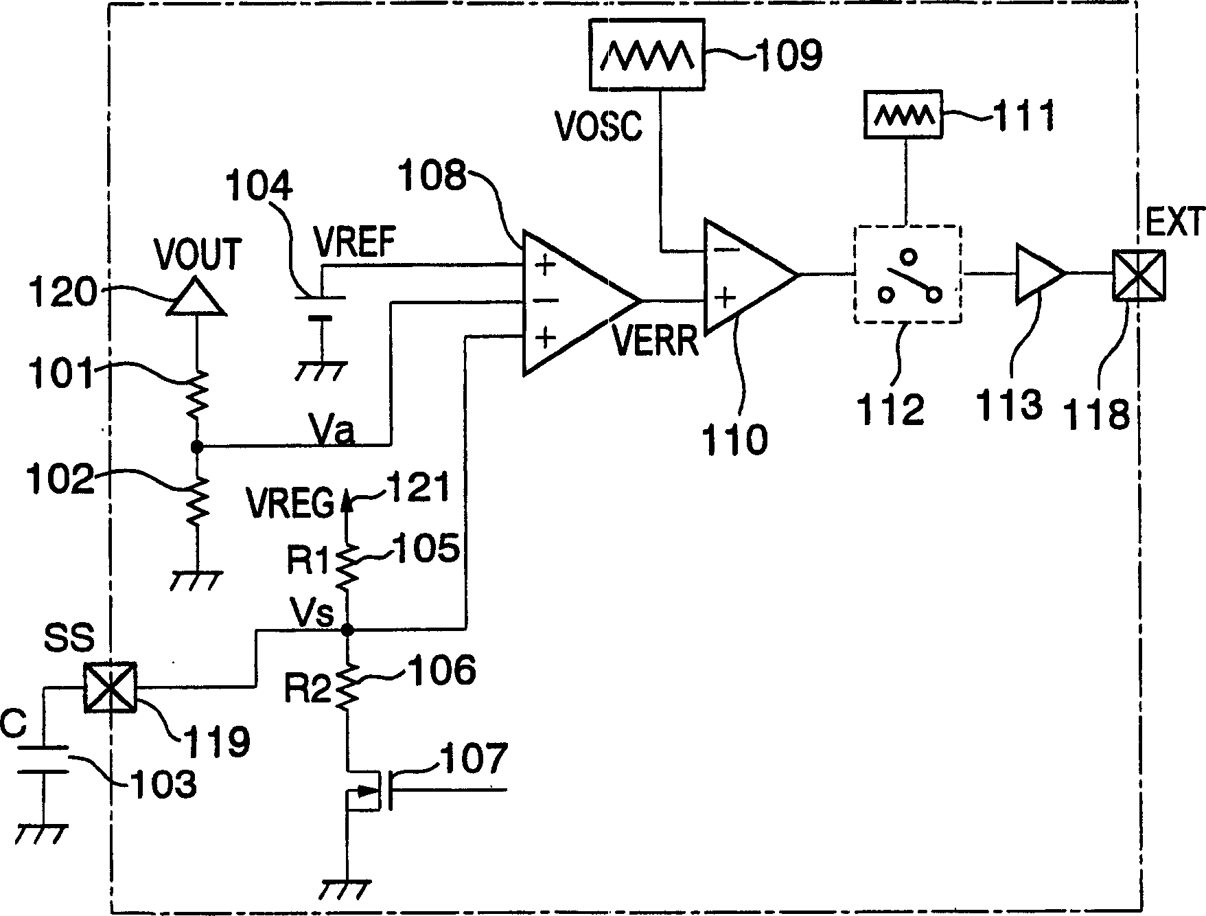
[0020] figure 1 is a schematic diagram showing a PWM switching regulator control circuit according to the present invention.
[0021] Basic operation is the same as conventional circuit except soft start. The error amplifier 108 outputs the difference between the feedback voltage Va obtained by dividing the output voltage VOUT by the voltage dividing resistors 101 and 102 and the voltage VREF output from the reference voltage circuit 104 as an output VERR. Then, the PWM comparator 110 outputs a comparison result between the output VERR of the error amplifier 108 and the output VOUT of the chopper oscillation circuit 109 .
[0022] The switch circuit 112 outputs a pulse signal to start the oscillation circuit 111 to the EXT terminal until the output voltage VOSC becomes a stable voltage. The pulse signal causes the external switch to ...
PUM
 Abstract
Description
Claims
Application Information