Water-saving time-delay valve device
A delay valve and water inlet valve technology, applied in water supply devices, flushing equipment with water tanks, buildings, etc., can solve the problems of laborious operation, friction, seal wear, dripping, etc., to reduce water leakage, prevent dust intrusion, mechanism simple and reliable effect
- Summary
- Abstract
- Description
- Claims
- Application Information
AI Technical Summary
Problems solved by technology
Method used
Image

Examples
Embodiment 1
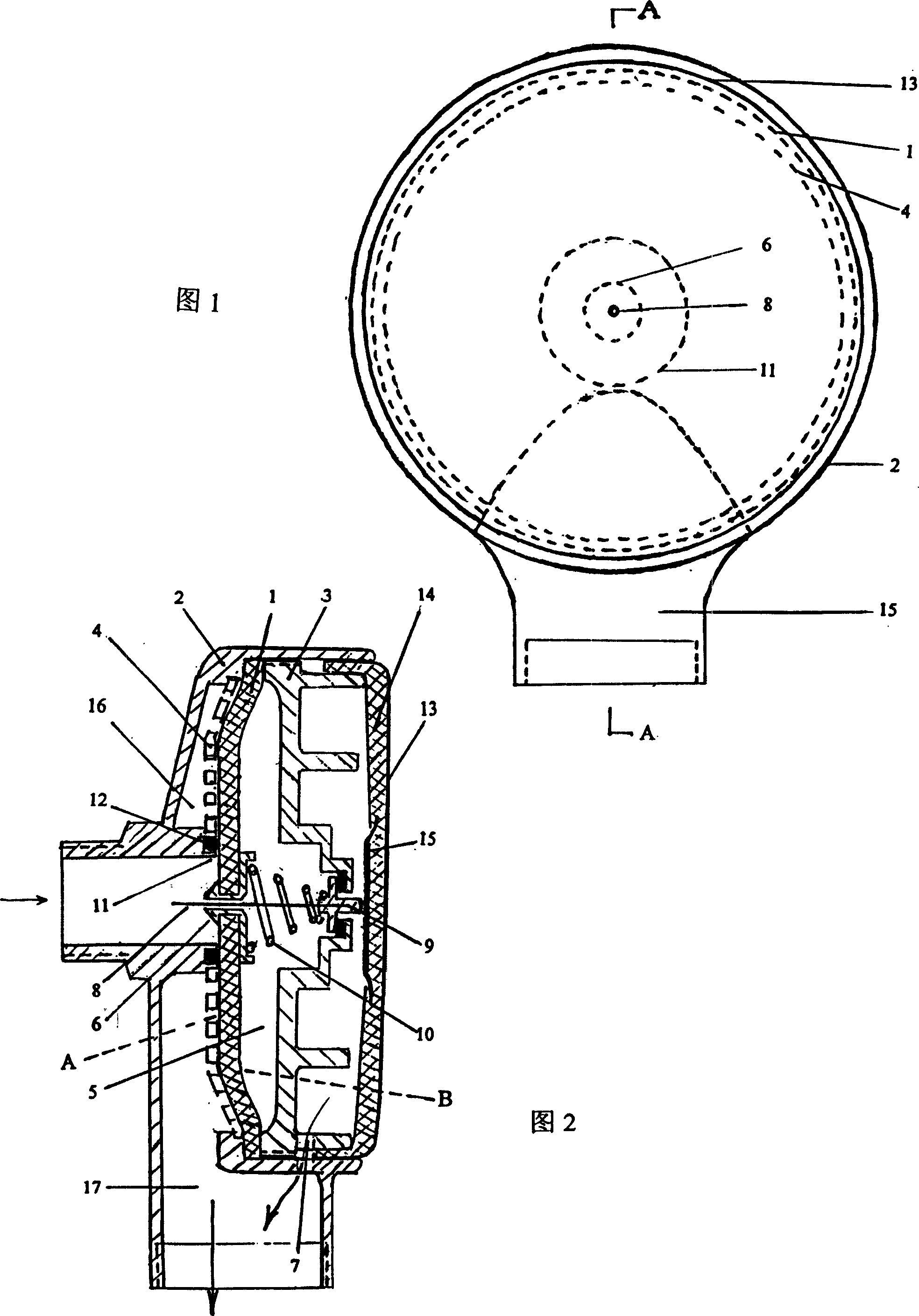
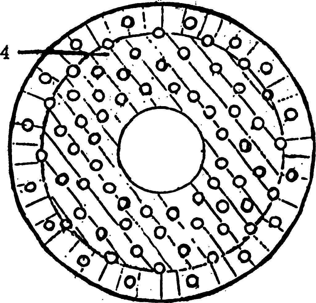
[0027] See Figure 1-2. The inlet and outlet valve seats (2) are connected to the self-inlet pipe. When it is normally closed, the water chamber (5) is filled with water, and its pressure is equal to that of the water supply, so that the A surface of the central diaphragm valve core (1) The middle part is flatly attached to the water inlet valve port (11). In order to make the seal more reliable, an "O" type rubber ring (12) can also be embedded in the ring end surface of the water inlet valve port (11) to form a central diaphragm valve disc against the " The two-way flexible sealing ring surface of the O” type rubber ring (12) is soft to soft, not the corresponding sealing surface of steel, and is clamped between the edges of the annular oblique concave wide groove drainage cavity (14) Porous stop ring (4) (see image 3 ) to limit the central diaphragm spool (1) to float unevenly within the set range, so as to avoid fatigue damage caused by deformation and transition. . When ...
Embodiment 2
[0029] see Figure 4 The invisible integral button cover (13) is a flexible reinforced glue layer (14) attached to the inner wall of the stainless steel sheet molding, and a solid gasket (15) is fixed in the middle of the glue layer to form an elastic outer steel inner flexible composite button cover (13). Press or step on the middle part, using its characteristic of small-scale unevenness, the solid washer (15) is linked with the "T" type pressure relief valve (9) to relieve the pressure of the water chamber cavity (5), and the flow through the pressure relief channel (7) Go, the central diaphragm spool (1) then deflects to the side of the water chamber cavity (5), which is equivalent to the drainage station where the valve clack is opened. The axial rear end of the "T" type pressure relief valve (9) can also be connected with a through needle (8) or a vortex vibrating needle (18) that can be rotated by water flow through the damping hole (6), so that each flushing of the toi...
Embodiment 3
[0033] The structural principle of this embodiment is basically the same as that of the previous embodiment, the difference is that the inlet and outlet pipes are connected to the pipeline in reverse phase (see Figure 6 ) shows that the central diaphragm valve core (1) is strengthened, that is, the reinforced bump (19) with a little thickness is added, and the damping hole (6) is riveted to the central diaphragm valve core (1), deviated from The center of the hole on one side of the center is inserted through the needle or the vortex trembling needle (18), and the same principle reaches the self-closing purpose of time delay, but the porous limit retaining ring (4) can be exempted. Because the central membrane spool (1) has the same water pressure on both sides except the central reinforcement area, the central membrane spool (1) will not be damaged.
PUM
 Abstract
Description
Claims
Application Information
 - R&D
- Intellectual Property
- Life Sciences
- Materials
- Tech Scout
- Unparalleled Data Quality
- Higher Quality Content
- 60% Fewer Hallucinations
Browse by: Latest US Patents, China's latest patents, Technical Efficacy Thesaurus, Application Domain, Technology Topic, Popular Technical Reports.
© 2025 PatSnap. All rights reserved.Legal|Privacy policy|Modern Slavery Act Transparency Statement|Sitemap|About US| Contact US: help@patsnap.com