Blower impeller

A blower blade and wheel hub technology, applied in the field of blower impeller, can solve the problems of difficult separation of resin and metal, poor recycling and reuse, etc., and achieve excellent effects of thermal deformation and damage rotation strength

Inactive Publication Date: 2005-02-16
PANASONIC CORP
View PDF1 Cites 6 Cited by
  • Summary
  • Abstract
  • Description
  • Claims
  • Application Information

AI Technical Summary

Problems solved by technology

But in this way, when recycling resources, it becomes difficult to separate the resin and metal; if they are crushed together, the recovered resources cannot be reused
Therefore, there is a problem of poor recyclability

Method used


Image

  • Blower impeller
  • Blower impeller
  • Blower impeller

Examples


Embodiment approach

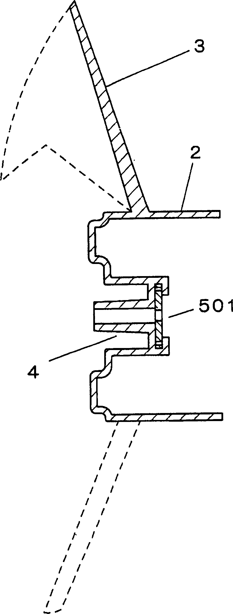
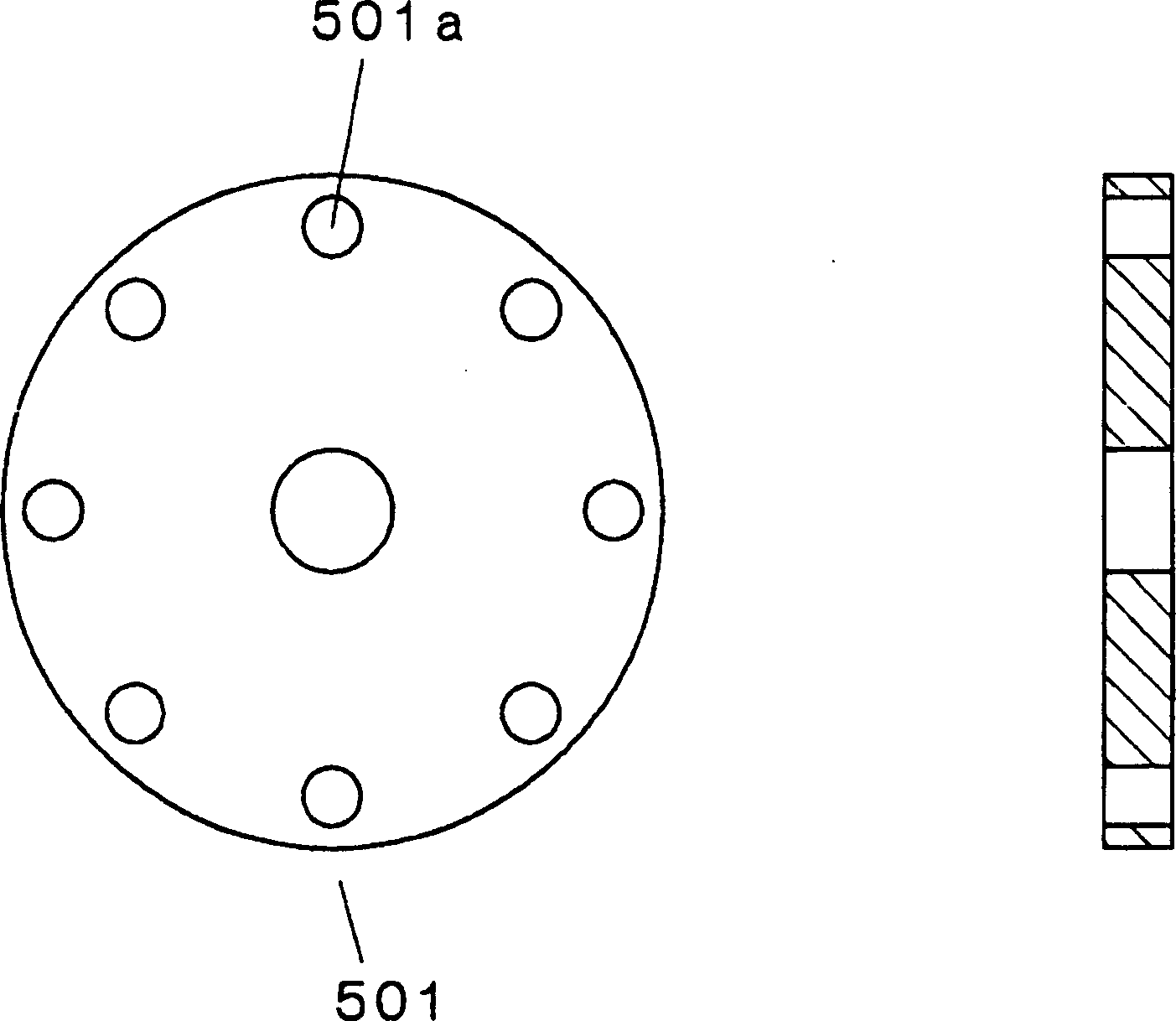
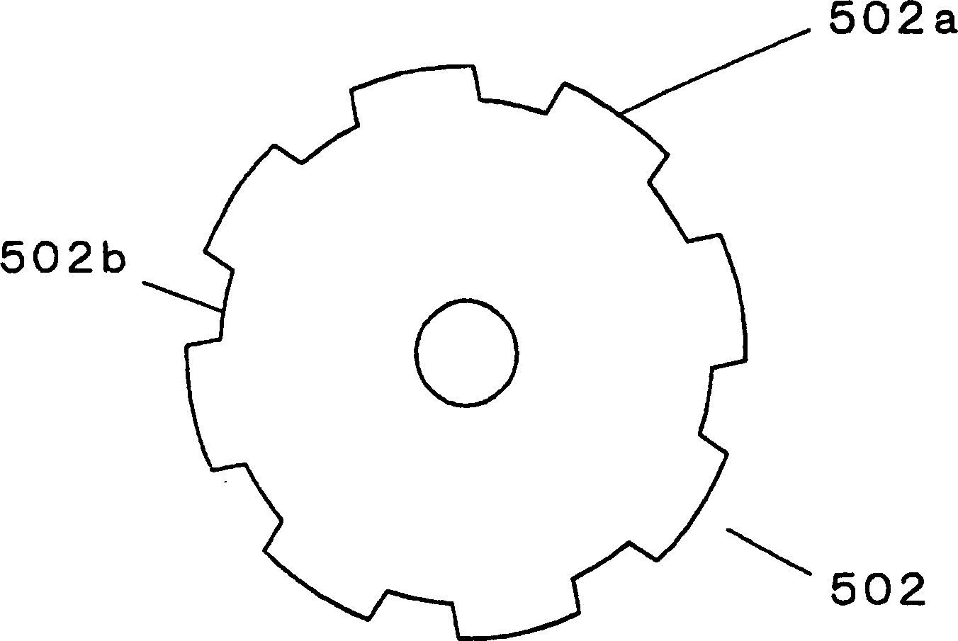
[0031] The embodiments of the present invention are described below with reference to the drawings and tables. figure 1 It is the first embodiment of the present invention. The figure shows a longitudinal cross-sectional view of a blower impeller of an air conditioner, in which a fixing member with a through hole near the outer edge is provided. figure 2 These are a plan view and a cross-sectional view of the fixing member of the first embodiment of the present invention. image 3 It is the second embodiment of the present invention, and is a plan view of a fixing member provided with tooth-like concavities and convexities on the outer edge. Figure 4 It is the second embodiment of the present invention, and is a top view of a fixing member with wave-shaped concavities and convexities on the outer edge. Figure 5 The oblique view of the appearance of the blower impeller. Fig. 6 is a longitudinal sectional view of a blower impeller of a conventional air conditioner. Figure 7 It ...


PUM

PropertyMeasurementUnit
flexural modulusaaaaaaaaaa
lengthaaaaaaaaaa
flexural modulusaaaaaaaaaa

Abstract

Provided is an impeller for a blower using a highly rigid resin at a flat component without using a metal flat component particularly at a bearing portion and having an improved recycling property. The impeller for the blower comprises a plurality of blades 3 around a hub 2. It has a cylindrical resin bearing portion 4 at the center of the hub for serving as a bearing for a motor shaft and a resin flat component 501 at the bearing portion for fixing the impeller for the blower to the motor shaft with a nut.

Description

Technical field [0001] The present invention relates to a blower impeller with excellent rigidity, heat resistance, and recycling properties. Background technique [0002] The structure of the existing blower impeller is generally as follows Figure 5 As shown in Figure 6, a plurality of wing-shaped blades 3 are provided around the cylindrical hub 2 to form the blower impeller 1. The motor shaft passes through the shaft sleeve part 4 located in the center of the impeller (used to be fixed to the motor), and then in the metal Nuts are screwed on the finished fixing piece 5 to fix the impeller to the motor shaft, so that the blower impeller rotates to generate blast (for details, please refer to Japanese Patent Laid-Open No. 9-228993). [0003] When it was first developed, the material of the blower impeller used metal materials such as steel plate or aluminum plate that was stamped and then coated with a variable surface. In recent years, under the trend of focusing on production ...

Claims


Application Information

Patent Timeline
Patent Type & Authority Applications(China)
IPC IPC(8): F04D29/34B29C45/14B29K23/00B29K55/00B29K105/16B29K105/20B29K509/08B29K509/10B29K623/00B29K677/00B29K709/08B29L31/08C08K3/34C08K7/14C08L23/10C08L23/16C08L25/08C08L33/08C08L33/18F04D29/38
Inventor 太田雅春
Owner PANASONIC CORP
Why Eureka
Try Eureka