
Suction optical disk unit speed-reducing device

A technology of deceleration mechanism and transmission components, which is applied in the direction of recording information storage, instruments, etc., and can solve problems such as wasting time

Inactive Publication Date: 2005-02-16
LITE ON IT
View PDF0 Cites 0 Cited by
  • Summary
  • Abstract
  • Description
  • Claims
  • Application Information

AI Technical Summary

Problems solved by technology

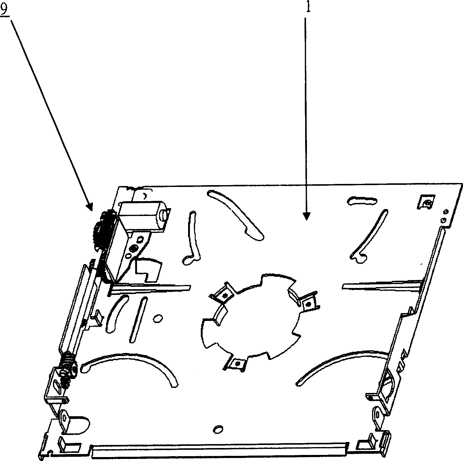
[0003] The deceleration mechanism 9 of known slot-in type optical disk drive is as figure 1 As shown, the speed reduction mechanism 9 must be fixed to the main body 1 before the optical disc player can be tested and searched for problems. If any component in the speed reduction mechanism 9 has a problem or cannot operate normally, the speed reduction mechanism 9 must be fixed. Some or all of the components in it are disassembled, replaced with new components and then re-tested, so it is quite time-consuming and inconvenient

Method used


Image

  • Suction optical disk unit speed-reducing device
  • Suction optical disk unit speed-reducing device
  • Suction optical disk unit speed-reducing device

Examples


Embodiment Construction

[0027] In order to further understand the features and technical contents of the present invention, please refer to the following detailed description and drawings related to the present invention. However, the drawings are only for reference and illustration, and are not used to limit the present invention.

[0028] Embodiments of the invention are described below in relation to slot-in disc players. However, the present invention is applicable to all optical disc players, including CD-ROM, CD-RW, Half Height, COMBO, DVD -R / RW disc players, external disc players and all optical media recorders and players etc.

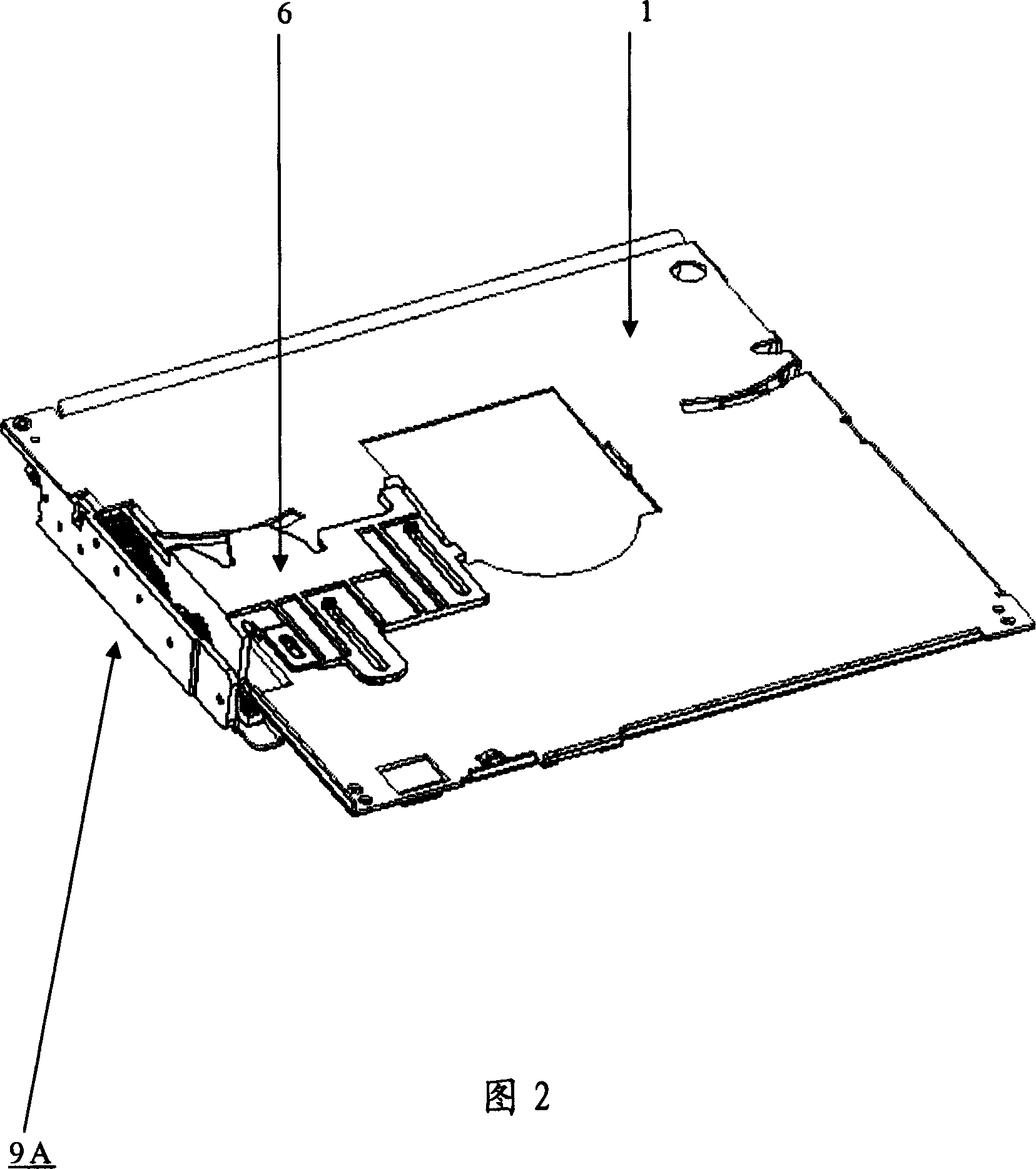
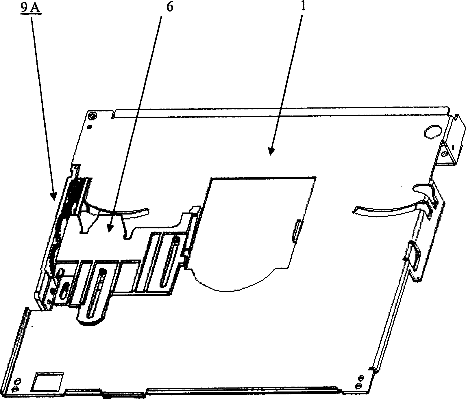
[0029] Figure 2 and image 3 Shown is a schematic diagram of a slot-in optical disk drive mechanism using the deceleration mechanism of the present invention, which has a main body 1, a slider 6 and a deceleration mechanism 9A; Figure 4 It is a schematic diagram of the mechanism relationship of the slot-in optical disc drive using the deceleration mechanism of the ...


PUM


Abstract

Disclosed modular designed reducing mechanism is capable of using space effectively, decreasing volume of optical disk drive. Moreover, the module of reducing mechanism can be tested solely. Being tested, trouble free reducing mechanism is assembled into optical disk drive so as to simplify testing and searching troubles for optical disk drive.

Description

technical field [0001] The present invention relates to a speed reduction mechanism for an optical disc player, and more particularly to a slot-in optical disc player. Background technique [0002] Recently, due to the continuous improvement of computer peripheral equipment, and its price is also constantly falling, among which, the price of the optical disk drive has been accepted by ordinary people. Using a slot-in optical drive allows users to easily load and eject discs. Slot-in CD players can be used in many electronic products, such as notebook computers and car CD players. The difference between the deceleration mechanism of the slot-in optical disc drive and the general tray-type optical disc drive is that its height is less than half of that of the tray-type half-height optical disc drive, so it has a very high design. Space requirements and display difficulty. [0003] The deceleration mechanism 9 of known slot-in optical disk drive is as figure 1 As shown, the...

Claims


Application Information

Patent Timeline
Patent Type & Authority Applications(China)
IPC IPC(8): G11B17/04
Inventor 郭宗荣
Owner LITE ON IT
Learn More