Light circular polarization modulator

A modulator and circular polarization technology, which is applied in the field of optical circular polarization modulators, can solve the problems of inability to polarize and modulate, and achieve the effects of convenient and fast modulation, satisfying fast modulation, and convenient detection

Inactive Publication Date: 2005-03-02
ZHEJIANG UNIV
View PDF0 Cites 5 Cited by
  • Summary
  • Abstract
  • Description
  • Claims
  • Application Information

AI Technical Summary

Benefits of technology

This technology allows us to create an opaque device that lets through only one type of electromagnetic radiation at once without affecting its other types of waves like radio signals transmitted by satellites. It uses this property to control how much energy it emits from different directions while still allowing them to pass freely between two states called state A and B. By controllably changing these properties, we have made possible new ways to make things look more natural when looking around with their surroundings (like being able to see if there are any objects). Additionally, they could detect even small amounts of materials such as drugs or chemical agents within our environment easily.

Problems solved by technology

This patented technical problem addressed in this patents relates to improving how well known linearly polarizers work with both left-right handed circularlypolarized lights (LHCP) and nonlinear ones such as birefringence (B), achromatic aberrator(ACOA).

Method used


Image

  • Light circular polarization modulator
  • Light circular polarization modulator

Examples


Embodiment

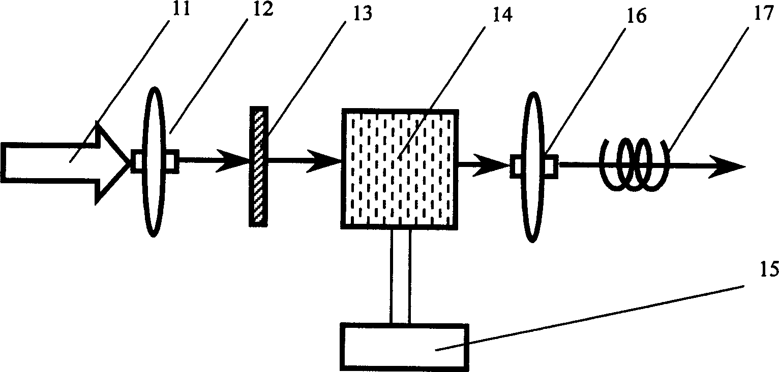
[0014] The following uses liquid crystal material as an example to illustrate the specific implementation of the present invention, but the implementation of the present invention is not limited to the use of liquid crystal material as the birefringent crystal.

[0015] figure 1 The schematic structure diagram of the present invention is shown, the natural light 11 passes through the input coupling device 12, enters the polarization optical device 13, and is converted into 45° linearly polarized light. In the figure, the polarizing optical device 13 and the crystal 14 with adjustable birefringence properties can be integrated and work as a whole, or work independently and step by step. Whether to work together or work independently and step by step depends on the selected material and modulation method, which is not absolute. When the linearly polarized light passes through the birefringence-tunable crystal 14, the modulation controller 15 is used to modulate the shape and lo...


PUM


Abstract

The invention discloses a light circular-polarization modulator, including a light input coupler, a light output coupler and at least a birefringent regulable crystal, where the crystal can change the shape or major axis orientation of its refractive index ellipsoid under the action of electric, magnetic, temperature and light fields or force, by this characteristic, able to modulate levorotary and dextral circularly-polarized lights, thus realizing the convenient and practical effect, and mainly applied to chiral substance detection and identification, communication coding and optical teaching.

Description


Claims


Application Information

Patent Timeline
Owner ZHEJIANG UNIV
Why Eureka
Try Eureka