Conveying system

A technology of transmission system and walking track, which is applied in the field of transmission system, and can solve problems such as difficult to use trolley 53, poor working efficiency, and time-consuming

Inactive Publication Date: 2005-03-09
SHINKO ELECTRIC CO LTD
View PDF0 Cites 3 Cited by
  • Summary
  • Abstract
  • Description
  • Claims
  • Application Information

AI Technical Summary

Problems solved by technology

[0007] However, the above-mentioned conveying system 50 has the following problem, that is, when loading and unloading the conveyed objects on the station 52a, and at the same time, when another trolley 53 conveys the conveyed objects loaded and unloaded by the station 52a, the second trolley 53 must Waiting on the conveying rail 51 in front of the station 52a, by such a waiting trolley 53,

Method used


Image

  • Conveying system
  • Conveying system
  • Conveying system

Examples


Embodiment Construction

[0029] Embodiments of the present invention will be described below with reference to the accompanying drawings.

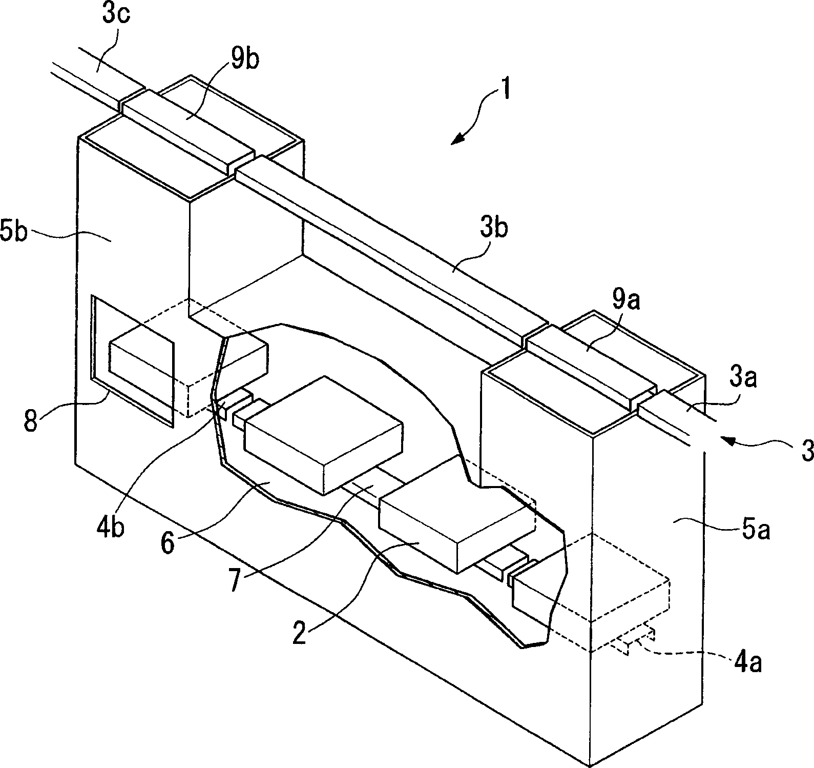
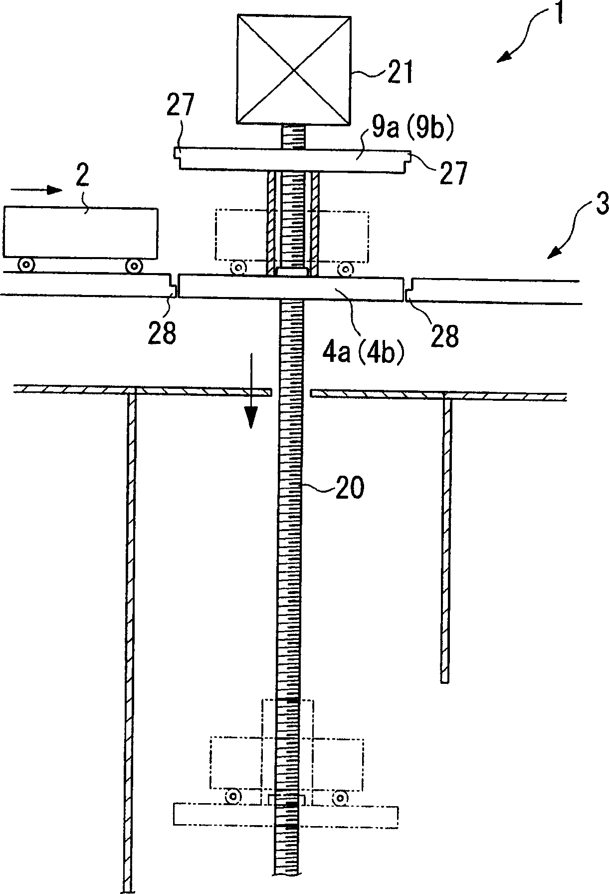
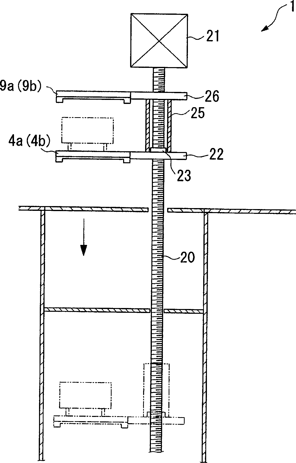
[0030] figure 1 It is a partially cutaway perspective view showing the main part of the transmission device (transmission system) that efficiently transmits various materials, samples, etc. in medical facilities, Figure 2-4 It is a front view and a side view showing the moving mechanism of the moving rail portion of the trolley.

[0031] In the delivery device given in this embodiment, as mentioned above Figure 5 As shown, a conveyor rail as a running rail is laid to pass through each room such as a consultation room, a treatment room, and an operating room in a medical facility, and a station for stopping a trolley traveling on the conveyor rail is installed in each room. The control of each trolley is automatically carried out by a control device not shown in the figure. When the sending operation is performed, the call-out control of the empty trolley that ...


PUM


Abstract

A conveying system allowing multiple trolleys to run on each station at the same time and high frequency is composed of the running track, multiple trolleys running along said running track, multiple movable track units on said running track, which can be separated from the running track and move in oblique direction, the connecting track unit for connecting multiple separated movable track units, and replacing track unit for replacing the separated movable track units to connect running track.

Description

technical field [0001] The present invention relates to a conveyor system, which is used in semiconductor manufacturing factories, hospitals, etc., and has a trolley movable along a running track. Background technique [0002] In recent years, in facilities such as semiconductor manufacturing plants and hospitals, the transport system has been widely used as a transport system for transporting objects to be transported. In this system, running rails are laid in the ceiling space of the facility, and tables for loading and unloading objects to be conveyed are installed in each room, and a trolley loaded with objects to be conveyed travels on the running rails between the tables. [0003] In the past, as the above-mentioned transmission system, it was known that there were Figure 5 , Image 6 type shown. Figure 5 The conveying system 50 shown comprises: a conveying rail 51 as a walking track, a plurality of stations 52a, 52b, 52c; a plurality of trolleys 53; The trolley 53...

Claims


Application Information

Patent Timeline
IPC IPC(8): B65G35/00B65G37/00B65G49/05B65H29/00
Inventor 富崎猛
Owner SHINKO ELECTRIC CO LTD
Why Eureka
Try Eureka