Ditch sludge cleaning device

A technology for cleaning device and silt, which is applied in the direction of earth mover/shovel, construction, etc., can solve the problems of uneven silt cleaning surface at the bottom of the canal, easy accumulation of raised silt parts again, uneven human control force, etc.

Inactive Publication Date: 2021-03-09
窦贤敏
View PDF8 Cites 1 Cited by
  • Summary
  • Abstract
  • Description
  • Claims
  • Application Information

AI Technical Summary

Problems solved by technology

[0006] Aiming at the deficiencies of the prior art, the present invention provides a canal sludge cleaning device, which solves the problem that the traditional canal dredging equipment needs to be manually cleaned by external force, and the workers cannot observe the position of the protrusion blockage, which consumes a lot of manpower and energy and is controlled manually. The uneven force will cause the mud cleaning surface at the bottom of the ditch to be uneven, and the raised mud parts will easily form a problem of accumulation again

Method used


Image

  • Ditch sludge cleaning device
  • Ditch sludge cleaning device
  • Ditch sludge cleaning device

Examples


Embodiment 1

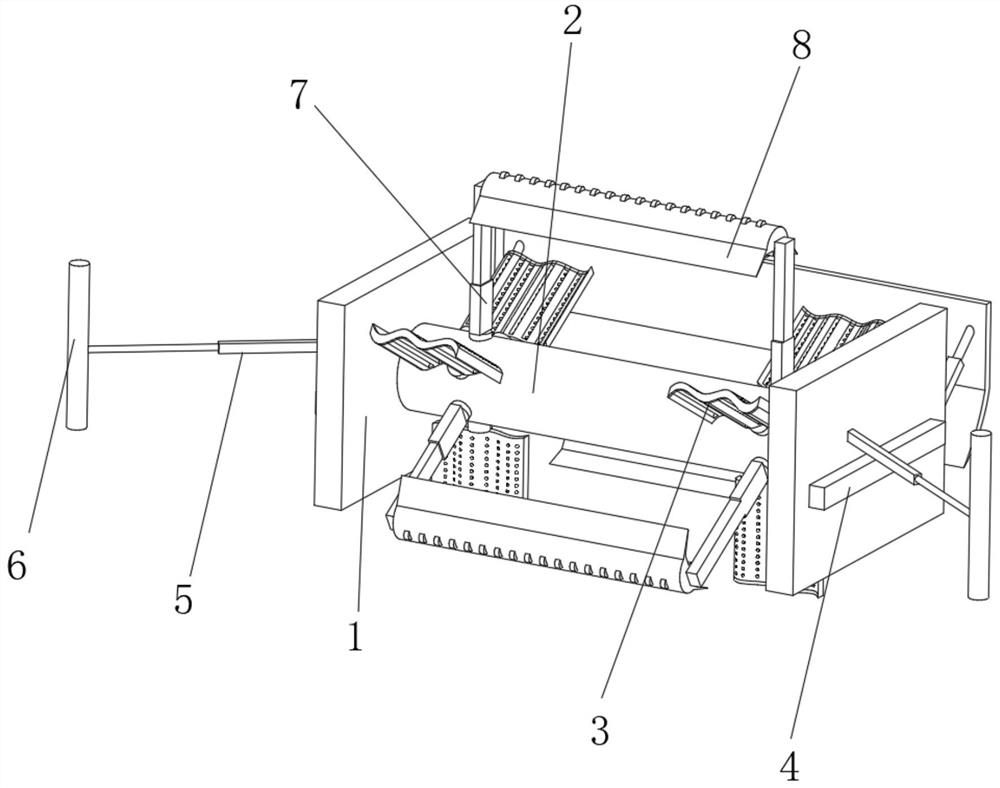
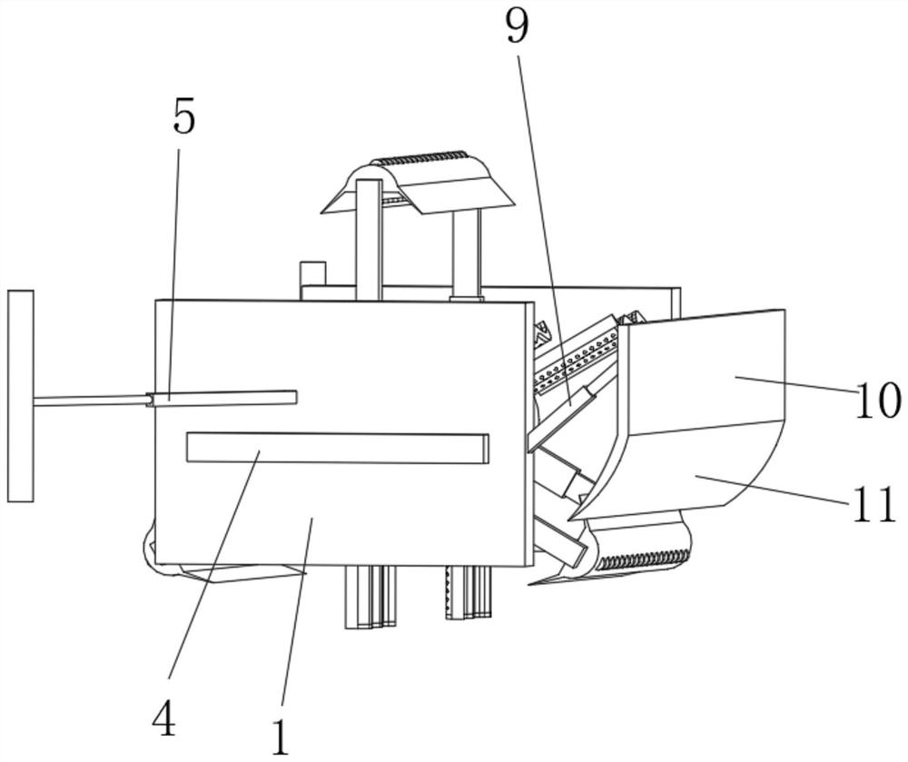
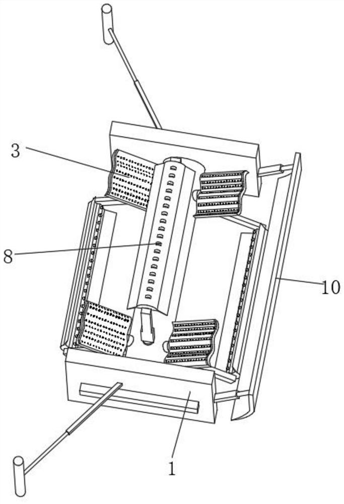
[0039] Such as Figure 1-3As shown, the present invention provides a technical solution: a device for clearing silt from a water channel, including a limiting outer frame 1, a drive shaft 2 is rotatably connected to the middle position of the inner limit of the outer frame 1, and the surroundings of the outer two ends of the drive shaft 2 The water diversion driving mechanism 3 is evenly and fixedly connected, and the middle position outside the drive shaft 2 is fixedly connected with a stable floating plate 4, and the middle of the outside of the drive shaft 2 and is located above the stable floating plate 4 is rotatably connected with a spring connecting rod 5, and the spring is connected One end of the rod 5 far away from the limit outer frame 1 is connected with a contact pressure roller 6, and the outer surface of the drive shaft 2 and the position between the water diversion drive mechanisms 3 are evenly and fixedly connected with a booster removal mechanism 7, and the to...

Embodiment 2

[0042] Such as Figure 4 As shown, on the basis of Embodiment 1, the present invention provides a technical solution: a device for clearing water canal silt, the water diversion drive mechanism 3 includes a drive baffle 301, and the bottom end of the drive baffle 301 is fixedly connected to the drive shaft 2 , the drive baffle 301 adopts a corrugated structure, and the surface of the drive baffle 301 is axially consistent with the drive shaft 2 .

[0043] The surface of one side of the driving baffle 301 is uniformly provided with a resistance-increasing inner groove 302 , and the inside of the resistance-increasing inner groove 302 is provided with a limiting perforation 303 , and the back of the limiting perforation 303 penetrates the driving baffle 301 . The water flow resistance area is increased to ensure the driving force for driving the shaft rod 2 to rotate.

Embodiment 3

[0045] Such as Figure 5 As shown, on the basis of Embodiment 1 and Embodiment 2, the present invention provides a technical solution: a kind of water channel sludge cleaning device. The drive shaft 2 is fixedly connected, and the top inside the booster rod 71 is penetrated and slidably connected with an extruding connecting rod 72 .

[0046] A booster inner groove 73 is provided at a vertical position inside the booster pole 71, and the booster inner groove 73 adopts a tapered structure with a large top and a small bottom.

[0047] The extruding connecting rod 72 is rotatably connected with a drive blade 74 at a position close to the bottom, and the bottom end of the extruding connecting rod 72 is fixedly connected with a restricting cone block 75 , which is correspondingly arranged with the pressurized inner groove 73 . Increases fluidity during water discharge and collection to avoid clogging.

[0048] The vertical position inside the extruding connecting rod 72 is fixedl...


PUM


Abstract

The invention discloses a ditch sludge cleaning device. The device comprises a limiting outer frame, a driving shaft rod is rotatably connected to the middle position of the inner side of the limitingouter frame, water diversion driving mechanisms are evenly and fixedly connected to the peripheries of the two ends of the outer portion of the driving shaft rod, and a stable floating plate is fixedly connected to the middle position of the outer portion of the driving shaft rod; pressurization removing mechanisms are evenly and fixedly connected to the position, between the water diversion driving mechanisms, of the outer surface of the driving shaft rod, scraping mechanisms are fixedly connected to the top output ends of the pressurization removing mechanisms, and a limiting adjusting rodis fixedly connected to the middle position of the back face of the limiting outer frame; and a water blocking pressing plate is fixedly connected to the end, away from the limiting outer frame, of the limiting adjusting rod, and a guiding arc plate is fixedly connected to the bottom end of the water blocking pressing plate. The invention relates to the technical field of ditches. According to theditch sludge cleaning device, the water flow speed and the water pressure are converted into walking kinetic energy of the cleaning device, and the cleaning device stably flows in a ditch.

Description

technical field [0001] The invention relates to the field of water canal technology, in particular to a water canal sludge cleaning device. Background technique [0002] Farmland irrigation often uses water from rivers and rivers, and introduces it into farmland through "ditches" opened on the ground. Canals are artificially dug waterways, which can be divided into main canals and branch canals. Main canals and branch canals are generally built with stone or cement. [0003] As the Chinese invention publication number is: a kind of towed canal dredging vehicle of CN104863197A. Its technical solution is: a towed canal dredging vehicle, which includes a flat car body with a dustpan-shaped opening, driving wheels arranged on both sides of the car body, and a wheel connected to the driving wheel and located in the dustpan-shaped opening. The stirring mechanism is provided with a dredging mechanism connected to it on the car body. The dredging mechanism includes a drive motor,...

Claims


Application Information

Patent Timeline
Patent Type & Authority Applications(China)
IPC IPC(8): E02F5/28
CPCE02F5/282E02F5/287
Inventor 窦贤敏
Owner 窦贤敏
Why Eureka
Try Eureka