Method for mfg optical elements

A technology for optical components and manufacturing methods, applied in manufacturing tools, glass pressing, glass manufacturing equipment, etc., can solve cumbersome problems and achieve the effect of high production efficiency and high surface accuracy

Active Publication Date: 2005-03-09
HOYA CORP
View PDF1 Cites 11 Cited by
  • Summary
  • Abstract
  • Description
  • Claims
  • Application Information

AI Technical Summary

Problems solved by technology

it's very tedious work

Method used


Image

  • Method for mfg optical elements
  • Method for mfg optical elements
  • Method for mfg optical elements

Examples


Embodiment 1

[0102] [Example 1: Manufacture of biconvex lens]

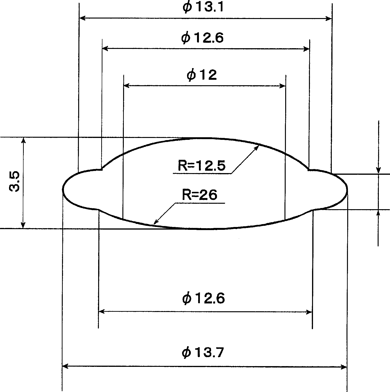
[0103] decide as follows image 3 The shape of the extrusion (including the portion removed by centering edging) is shown. exist image 3 Among them, the lens is a biconvex lens with R (paraxial radius of curvature) = 12.5 (in mm, the same below) on the first surface, R (same as above) = 26 on the second surface, a central wall thickness of 3.5, and an outer diameter of φ12 ( Final shape after centering and edging).

[0104] 1. The volume of the lens to be obtained is calculated as 270mm 3 . This can be calculated using lens design software.

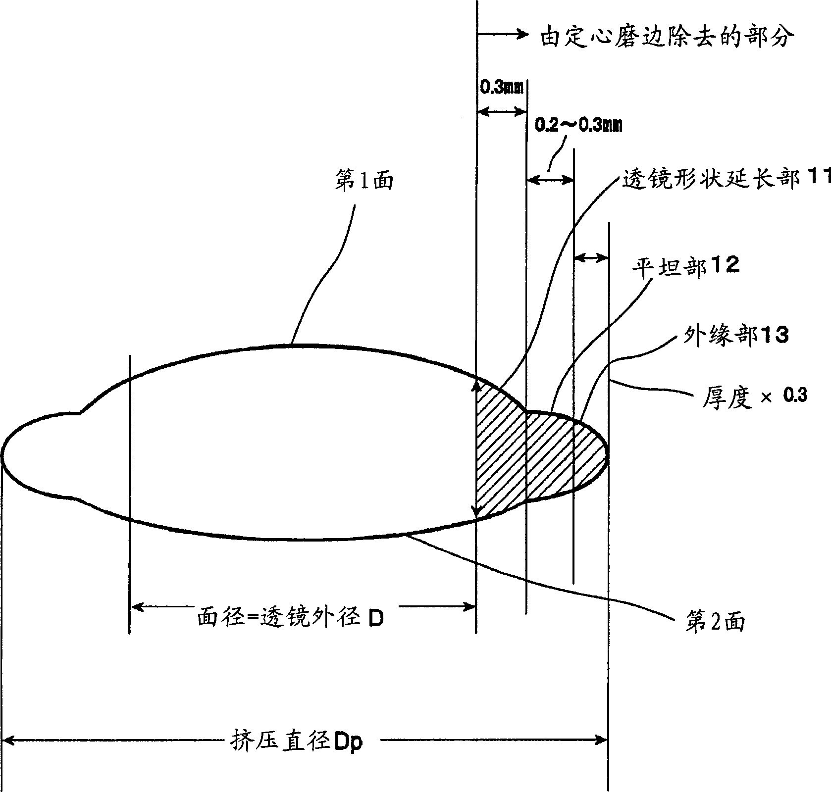
[0105] 2. On the first surface of the lens, an extension part (R=12.5) with a single side of 0.3 (R=12.5), φ12.6, is provided outside the outer diameter of the lens.

[0106] 3. On the second surface of the lens, also set an extension part (R=26) of 0.3 on one side, φ12.6.

[0107] 4. On the outside of the lens shape extension part of the first surface and the second surface of th...

Embodiment 2

[0114] [Example 2: Manufacture of concave meniscus lens]

[0115] The shape of the extruded product (including the portion removed by centering edging) shown in FIG. 5 was determined as follows. In Fig. 5, R (paraxial radius of curvature) of the first surface of the lens = 60 (in mm, the same below), R = 5.2 of the second surface (concave surface), and the surface diameter of the second surface is φ8.5. The lens A concave meniscus lens with a central wall thickness of 1.2 and a lens outer diameter of φ12 (final shape after centering and edging).

[0116] 1. The volume of the lens is calculated by using the lens design software to be 300mm 3 .

[0117] 2. On the first surface of the lens, set an extension part (R=60) with a single side of 0.3 on the outside of the lens outer diameter, φ12.6.

[0118] 3. Set a flat part (φ13.1) with a width of 0.25 on one side on the outside of φ12.6 on the first surface of the lens

[0119] 4. On the outer side of the second surface of the ...


PUM

PropertyMeasurementUnit
weightaaaaaaaaaa
refractive indexaaaaaaaaaa

Abstract

A method of manufacturing optical elements in which a precision-processed pressing mold is used and the molding surface thereof is transferred to a heat-softened preformed molding material to form an optically functional surface. In the method, post processing for centering and edging are conducted following precision pressing to determine the center axis of an optical element and / or to form on the periphery of the optical element a portion for mounting on some other component. The preformed molding material has a weight within a range of 110 to 155% of a weight of the optical element when the optical element has a biconvex or convex meniscus shape. The preformed material has a weight within range of 180 to 240% of a weight of the optical element when the optical element has a biconcave or concave meniscus shape.

Description

technical field [0001] The present invention relates to a manufacturing method of an optical element in which an optical function surface is formed by replicating its molding surface on a heated and softened molding material using a precisely processed molding die. In particular, the present invention relates to a method of manufacturing an optical element in which an optical axis of an optical element is determined by centering and edging after precision extrusion, or a mounting portion for other components is formed on the periphery of the optical element. Background technique [0002] As a method for producing optical elements, there is known a precision extrusion method in which optical elements such as lenses are formed by extrusion molding preformed molding materials such as glass preforms in a heated and softened state. The optical functional surface of the optical element obtained by precision extrusion does not need to be processed after cutting, grinding, etc., and...

Claims


Application Information

Patent Timeline
Patent Type & Authority Applications(China)
IPC IPC(8): C03B7/12C03B11/08
CPCC03B11/08C03B2215/49C03B7/12Y02P40/57
Inventor 泽田浩之高井直树樱井美由纪广田慎一郎
Owner HOYA CORP
Why Eureka
Try Eureka