
Pressing and mounting device for pressing and mounting thin-wall sleeve

A technology of press-fitting device and thin-wall sleeve, which is applied in the direction of metal processing, metal processing equipment, manufacturing tools, etc., can solve problems such as the difficulty of press-fitting thin-wall sleeves, and achieve high shape accuracy, high-pressure mounting accuracy, and convenient operation Effect

Active Publication Date: 2010-06-23
ANHUI JIANGHUAI AUTOMOBILE GRP CORP LTD
View PDF0 Cites 19 Cited by
  • Summary
  • Abstract
  • Description
  • Claims
  • Application Information

AI Technical Summary

Problems solved by technology

[0004] In order to solve the difficult problem of press-fitting thin-walled sleeves, the invention provides a press-fitting device for press-fitting thin-walled sleeves

Method used

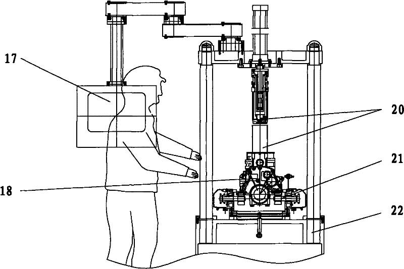

Image

  • Pressing and mounting device for pressing and mounting thin-wall sleeve
  • Pressing and mounting device for pressing and mounting thin-wall sleeve
  • Pressing and mounting device for pressing and mounting thin-wall sleeve

Examples


Embodiment Construction

[0031] Below in conjunction with accompanying drawing, the present invention will be further described by examples.

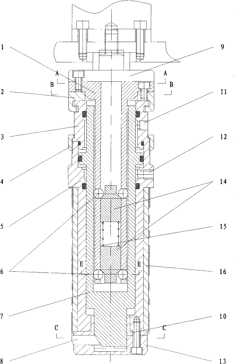
[0032] see figure 1 , a press-fitting device for press-fitting a thin-walled sleeve includes a base shaft 1, a sliding sleeve 7, an upper floating retaining sleeve 3, a lower floating retaining sleeve 5, and a copper sleeve 16, etc., and the upper end of the press-fitting device is connected to a flange 9 of a hydraulic cylinder .

[0033] The base shaft 1 is a hollow shaft, the upper end of which is a disc surface, and the threaded holes for connecting the flange 9 of the hydraulic cylinder and the bolt holes for connecting the fixed blocks are evenly distributed on the disc surface, see Figure 4 , the bottom surface of the disc surface is connected by bolts to install two semi-circular fixed blocks 2, see Figure 5 , The inner side of the semi-circular fixed block 2 is radially provided with an annular slot. Four steel ball holes are evenly distributed o...


PUM


Abstract

The invention relates to a device for pressing and mounting a thin-wall sleeve, which can solve the problem that the thin-wall sleeve is difficult to press and mount. The device comprises a press head, a basic shaft, a sliding sleeve, an upper floating retention sleeve, a lower floating retention sleeve, a copper sleeve and the like. The upper end face of the basic shaft is provided with a flange plate which is coaxially connected on a fixed fixture block by screws, an annular clamping groove of the fixed fixture block is clamped and hooped on a shaft journal at the upper part of the upper floating retention sleeve, the lower floating retention sleeve is coaxially positioned at the lower part of the upper floating retention sleeve, the upper floating retention sleeve and the lower floating retention sleeve are connected into a whole by the nuts of the retention sleeves, and the copper sleeve is sleeved and arranged on the lower floating retention sleeve. The sliding sleeve is arranged in the upper floating retention sleeve and the lower floating retention sleeve, and the middle part of the external diameter of the sliding sleeve is provided with a piston ring; and the lower half section of the sliding sleeve is provided with a solid shaft, and the end face of the solid shaft is provided with three centripetal tapered wedge T-shaped grooves which are uniformly distributed along a circumferential direction. The device has simple structure and convenient operation and can carry out pressing and mounting motions as long as the thin-wall sleeve is sleeved into the press head and a jack catch of a control button extends out, so that the parts of the thin-wall sleeve obtain higher pressing and mounting accuracy, and the effective guarantee is provided for enhancing the quality of a class of cylinder body.

Description

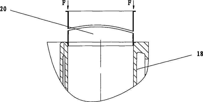
technical field [0001] The patent of the present invention relates to a press-fit thin-wall sleeve device. Background technique [0002] The thin-walled sleeves in the engine cylinder bore should generally have the characteristics of oil storage, lubrication and wear resistance. Therefore, for the thin-walled sleeves, the requirements for higher surface finish and shape accuracy are the guarantee for it to reflect its characteristics. And its assembly quality plays a vital role in the operation of cylinder parts. [0003] The current method of press-fitting the thin-walled sleeve is to place the thin-walled sleeve directly on the orifice of the assembled part, see image 3 , using the chamfer guide of the part hole to be assembled, because the part hole chamfer guide is short, and in the process of pressing, the pressure head directly contacts with the thin-walled sleeve and transmits the pressure. Both are easy to be skewed and deformed, resulting in a decrease in the cyli...

Claims


Application Information

Patent Timeline
IPC IPC(8): B23P19/027
Inventor 吴成龙梅勇张青锋
Owner ANHUI JIANGHUAI AUTOMOBILE GRP CORP LTD
Learn More