
Method for giving cane roller batch code to organzine coiling device

A coiling device and batch technology, applied in warping machines, rewinding machines, other manufacturing equipment/tools, etc., can solve problems such as inability to manage warp beams, batch code assignment errors, etc.

Inactive Publication Date: 2005-03-09
TSUDAKOMA KOGYO KK
View PDF2 Cites 3 Cited by
  • Summary
  • Abstract
  • Description
  • Claims
  • Application Information

AI Technical Summary

Problems solved by technology

[0019] If the update or correction of the batch code is forgotten as described above, the wrong batch code will be assigned to the warp beam, and the wrong batch code will be assigned to the warp beam, and the warp beam for weaving cannot be correctly managed.

Method used


Image

  • Method for giving cane roller batch code to organzine coiling device
  • Method for giving cane roller batch code to organzine coiling device
  • Method for giving cane roller batch code to organzine coiling device

Examples


Embodiment Construction

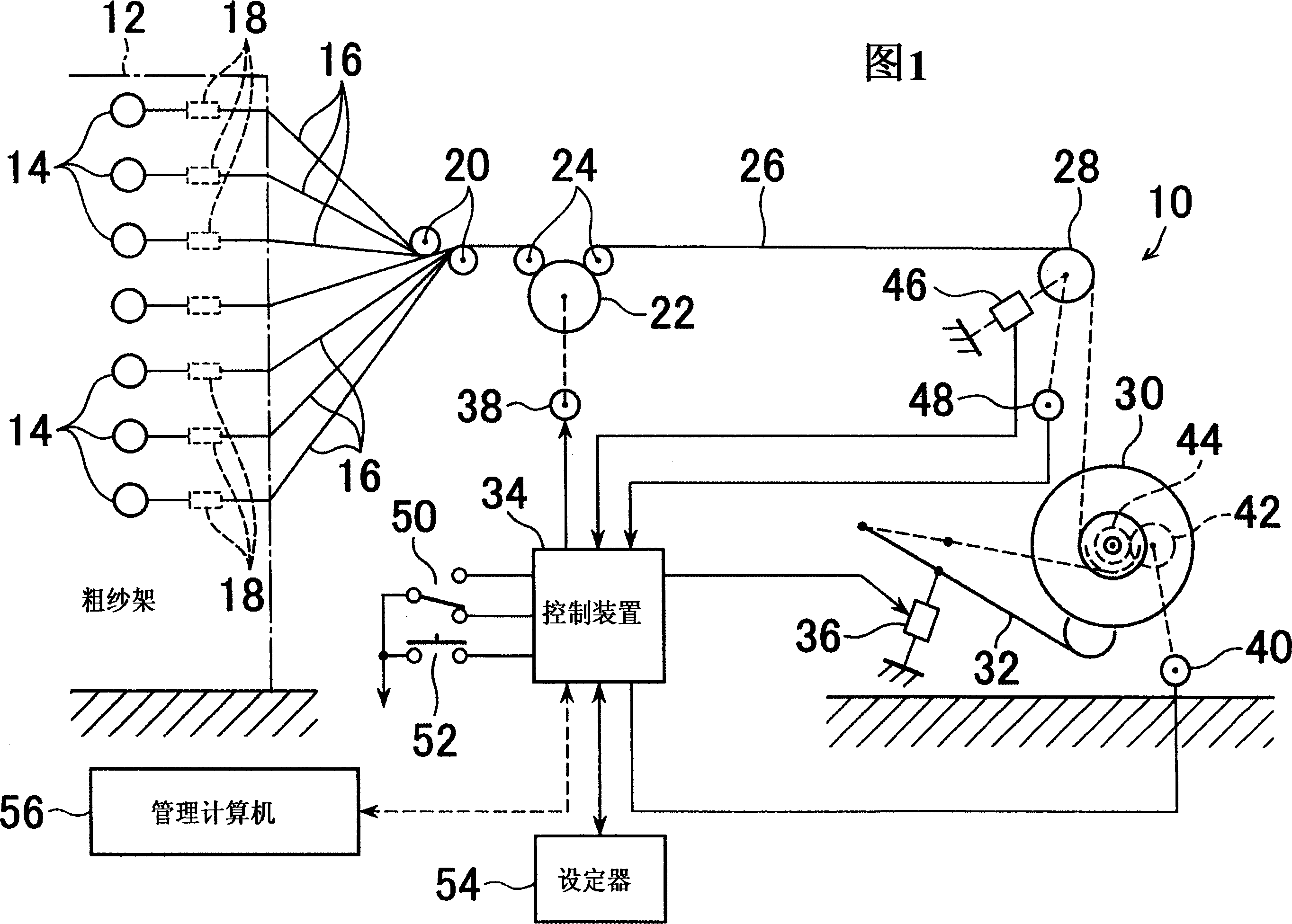
[0034] With reference to Fig. 1, warp thread take-up device 10, the many warp threads 16 that are respectively wound on a plurality of thread supply bodies 14 on the roving frame 12 are pulled out through the tensioner 18 on each warp thread, and the pulled out The warp yarns 16 are arranged side by side in sheet form with a pair of guide rollers 20, and these warp yarns 16 are sent out in the form of warp yarn sheets 26 with a take-up roll 22 and a pair of pressing rollers 24.

[0035] The warp yarn sheet 26 is wound up on the take-up warp beam 30 by the tension roller 28 which detects the tension acting on the warp yarn sheet 26 . The take-up warp beam 30 is connected to the driving motor through a connecting mechanism not shown in the figure, and is supported on a rotatable frame not shown in the figure simultaneously.

[0036] The supporting arm 32 is supported on the device frame (not shown in the figure) and can be rotated at an angle around an axis protruding horizontal...


PUM


Abstract

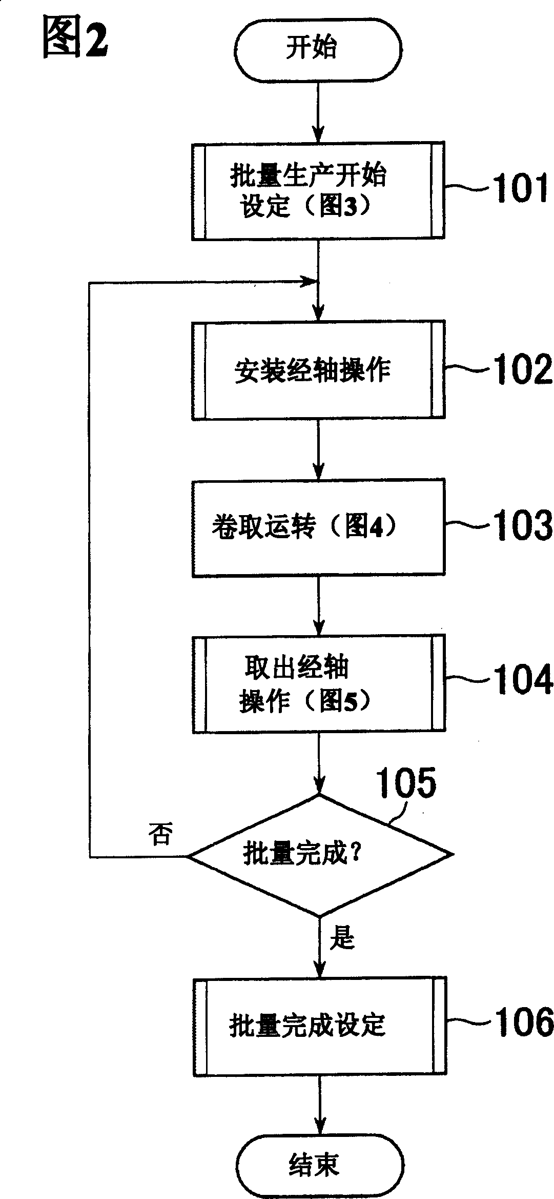
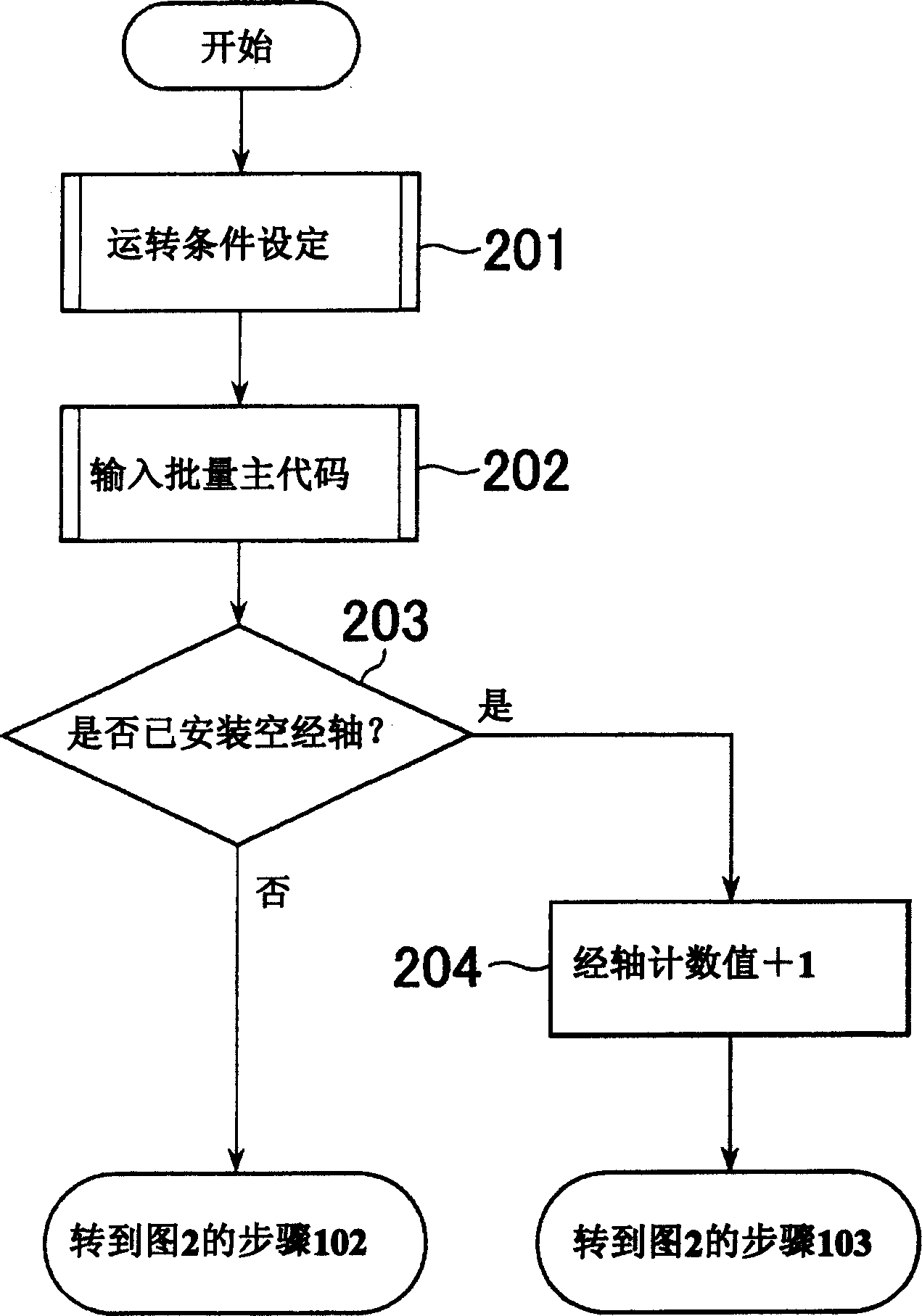
This method for imparting the lot code to the winding beam comprises inputting a parent code showing the lot and setting a lot start for returning a counting value for showing the order of the warp-winding beam on the production of the lot to an initial value, when the production of a new lot is started, adding one to the counting value, when a beam-loading or unloading operation is carried out after the setting of the lot start, comparing the winding length of the warp on the beam with a threshold value determined in response to a preparing operation period, and fixing a code obtained by combining the parent code with a child code corresponding to the counting value, as a lot code, after the winding length reaches the threshold value, and then imparting the fixed code to the beam.

Description

technical field [0001] The present invention relates to a method for assigning batch codes to winding warp beams of warp yarn winding devices. Background technique [0002] Warp yarns for weaving are subjected to various treatments in the warp yarn preparation stage. In this warp preparation stage, warp beams for weaving are continuously produced. These warp yarn warp beams are wound up so that a plurality of warp yarns can be pulled out in the shape of these warp yarn sheets arranged in parallel. [0003] A warp yarn winding device that continuously produces multiple warp beams by winding a predetermined length of warp yarns supplied according to a production lot is a type of warp yarn preparation machine that prepares warp yarns for weaving. [0004] As an example of such a warp winding device, there are the following devices. [0005] A device that arranges a plurality of warp yarns drawn from a plurality of roving creels into a sheet and winds the warp yarn sheet on a...

Claims


Application Information

Patent Timeline
IPC IPC(8): D02H5/00D02H3/00D02H13/28D03D51/00
Inventor 西村勋
Owner TSUDAKOMA KOGYO KK
Learn More