Uniform speed flow measuring device possessing speed raising function

A flow measurement device and function technology, applied in the field of average velocity flow measurement devices, can solve the problems of no uniform velocity, narrow pipe diameter application range, etc., achieve good uniform velocity performance, increase the signal boosting function, and improve the radial automatic uniform velocity effect of function

Inactive Publication Date: 2005-03-09
温汉璋
View PDF2 Cites 6 Cited by
  • Summary
  • Abstract
  • Description
  • Claims
  • Application Information

AI Technical Summary

Problems solved by technology

[0003] The present invention overcomes the problems of the prior art that there is no uniform velocity function and the applicable range of the pipe diameter is narrow

Method used


Image

  • Uniform speed flow measuring device possessing speed raising function
  • Uniform speed flow measuring device possessing speed raising function
  • Uniform speed flow measuring device possessing speed raising function

Examples


Embodiment 1

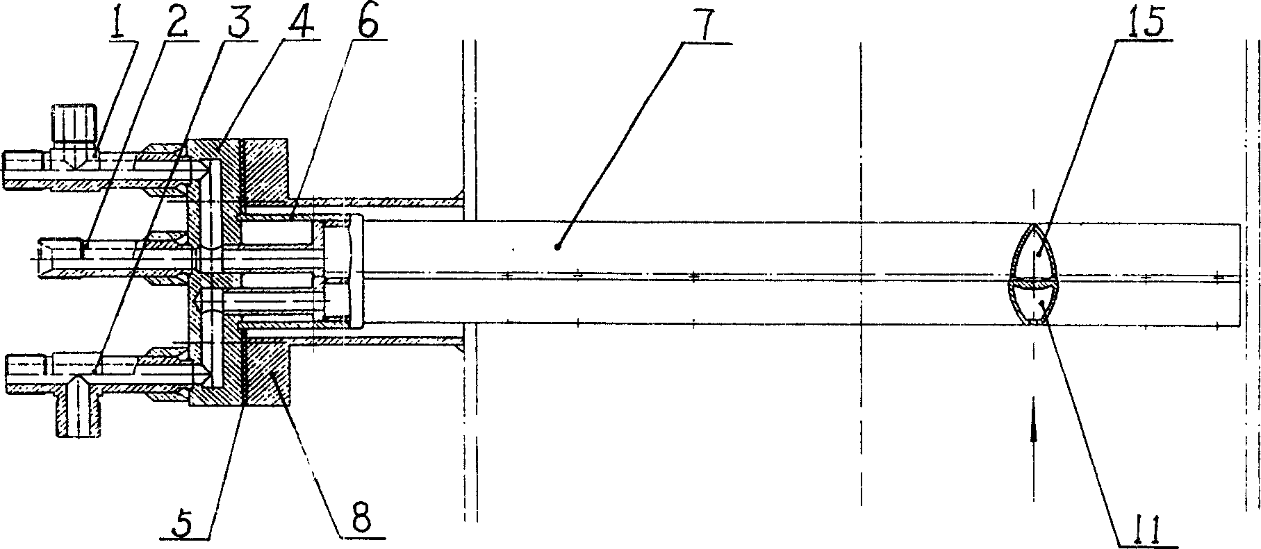
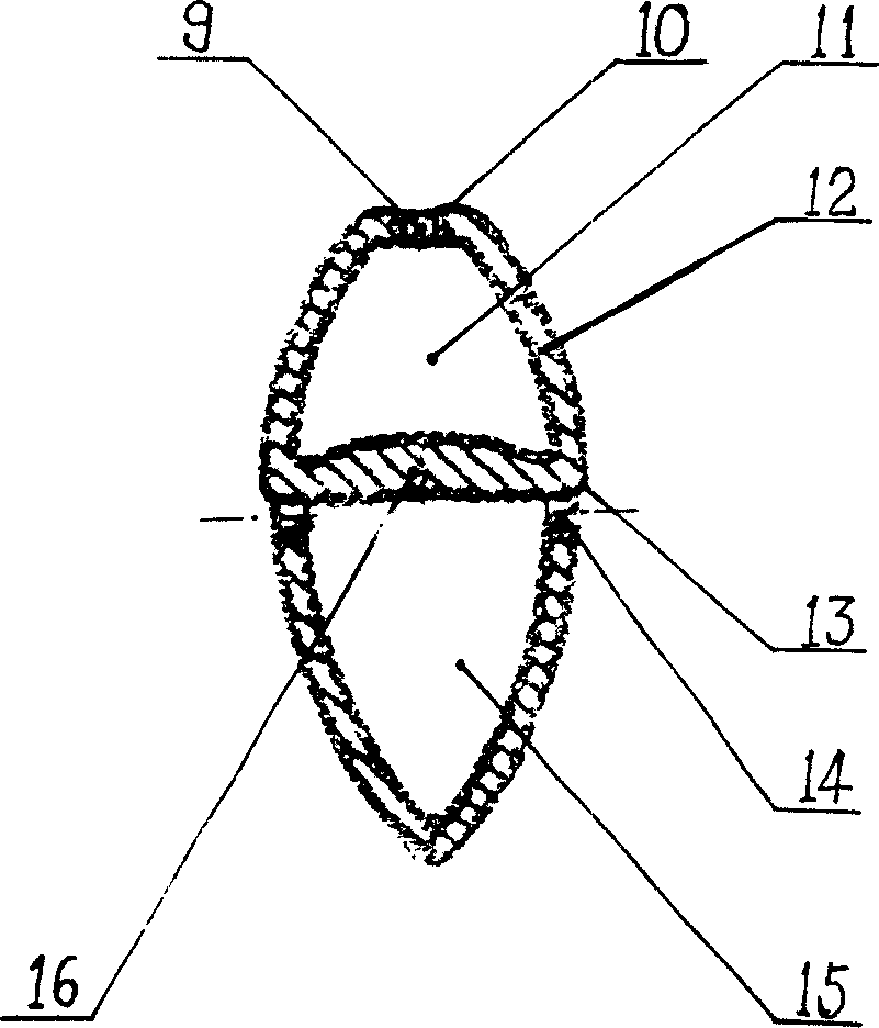
[0026] Example 1, see figure 1 , figure 2 . The product described in this embodiment 1 is composed of a measuring rod 7, a reinforcing sleeve 6, a mounting base 8, a sealing gasket 5 and a connecting head. Said measuring rod 7 is welded and installed on the lower side of the flanged connection plate 4 in the joint head. Three connection nozzles are installed on the upper surface of the flange connection plate 4: the total pressure connection nozzle 3, the temperature socket 2 and the static pressure connection nozzle 1, and there is also one on the total pressure connection nozzle 3 and the static pressure connection nozzle 1 Blow out the nozzle. Said measuring stick 7 cross section is " big head fish " shape, is made of total pressure pipe 11 and static pressure pipe 15 . The section of the tube wall 12 of said total pressure tube 11 and static pressure tube 15 is made of symmetrical arc and shared dividing plate 16 respectively, and the arc of total pressure tube 11 is ...

Embodiment 2

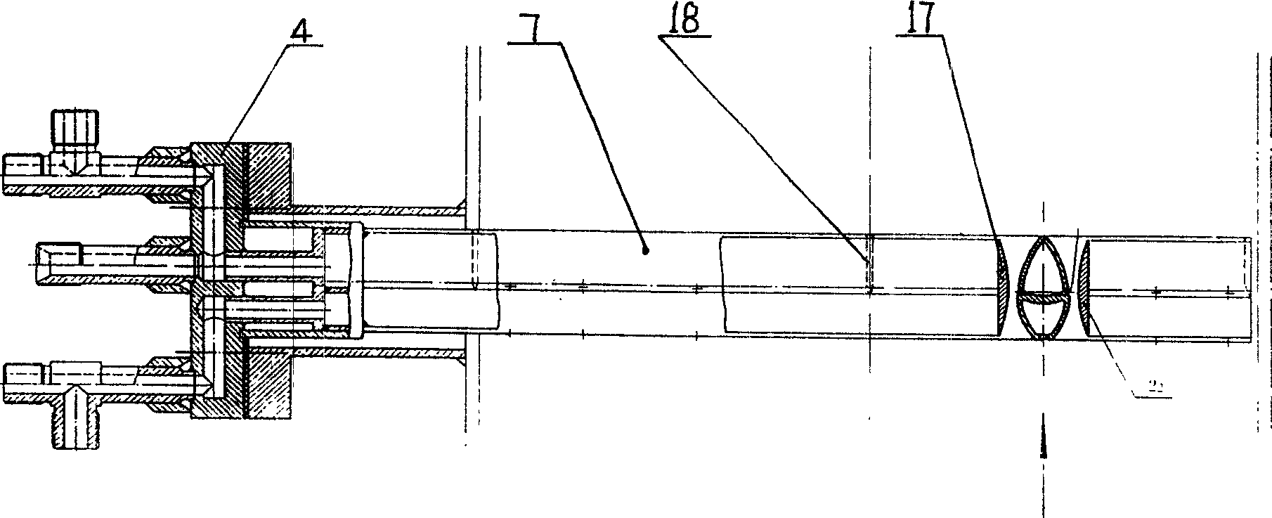
[0028] Example 2, see image 3 , Figure 4 . This program is improved on the basis of the measuring stick 7 described in Example 1, and its difference from Example 1 is that a speed-up plate 17 is added on both sides of the measuring stick 7, and the speed-up plate 17 is based on the measuring stick The axis of symmetry of the section is symmetrical and parallel to the measuring rod 7. The cross-section of the speed-raising plate 17 is equal in length to the cross-section of the measuring rod 7. The inner profile of the section is an arc line, and the outer profile is a straight line. A plurality of positioning partitions 18 are arranged along the length direction between the measuring rod 7 and the speed-increasing plate 17, and the measuring rod 7 is divided into two or more rectangular Venturi nozzles with precise dimensions. Taking pipe diameter D=400mm as an example, five positioning partitions 18 are set to divide the measuring rod 7 into four rectangular Venturi nozzl...


PUM


Abstract

The present invention relates to a device for measuring flow rate of fluid, in particular, it is an even-speed flow rate measuring device with the function of raising speed. Said device includes measuring rod and connection joint, and said measuring rod consists of total pressure tube and static pressure tube, the widths of the total pressure tube and satic pressure tube in the shared diaphragm position are widest, and the width of said total pressure tube is greater than that of static pressure tube; on the measuring rod several groups of total pressure and static pressure pressure-extracting points are set, and the total prssure pressure-extracting hole is set in the connected position of symmetrical arc lines of tube wall of total pressure tube, and the static pressure pressure-extracting hole is set on the tube wall of static pressure tube closed to diaphragm, and on the outside of the above-mentioned measuring rod two parallel speed-raising plates are symmetrically placed along the axial direction of measuring rod.

Description

Technical field: [0001] The invention relates to a device for measuring fluid flow, in particular to an average speed flow measuring device with speed increasing function. Background technique: [0002] With the rapid development of electronic technology, the development of flow measurement secondary instruments has reached a very high level, but the development of flow measurement primary instruments is relatively slow, and there are many deficiencies. Invented two patent technologies with patent numbers "98 2 32751.X" and "00 2 34506.4". However, in actual use, some new problems have been discovered: 1. Design according to the average speed point, without the function of average speed: In the actual process flow of the use site, the length of the straight pipe section of the given large pipeline flowmeter is relatively short and Diversified types of resistance parts lead to non-standard flow fields and odd changes in the cross-sectional flow velocity distribution of each ...

Claims


Application Information

Patent Timeline
Patent Type & Authority Applications(China)
IPC IPC(8): G01F1/34G01F1/44
Inventor 温汉璋
Owner 温汉璋
Why Eureka
Try Eureka