Back-to-light module

A backlight module and light source technology, which is applied in optics, optical filters, nonlinear optics, etc., can solve the problems of difficult lamp manufacturing process and inability to completely filter ultraviolet rays, and achieve convenient and simple procedures, save manufacturing costs, and facilitate heavy industry Effect

Inactive Publication Date: 2005-03-09
AU OPTRONICS CORP
View PDF0 Cites 5 Cited by
  • Summary
  • Abstract
  • Description
  • Claims
  • Application Information

AI Technical Summary

Problems solved by technology

[0003] However, the traditional way of coating filter material on the outer wall of the lamp tube often makes the lamp tube manufacturing process difficult and cannot completely filter ultraviolet rays.

Method used


Image

  • Back-to-light module
  • Back-to-light module

Examples


Embodiment Construction

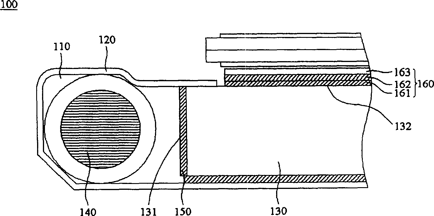
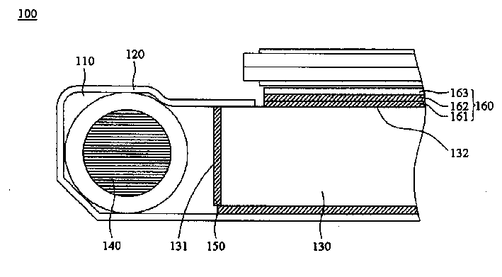
[0008] figure 1 It is the first embodiment of the backlight module of the present invention. The backlight module 100 has a cavity 110 formed by a first plate and a second plate. In this embodiment, the first plate is a reflective plate 120, the second plate is a light guide plate 130, and the light guide plate 130 has a light incident surface 131 and a light-emitting surface 132 ; the lamp tube 140 as a light source is disposed in the cavity 110 , the light emitted by the lamp tube 140 enters the light guide plate 130 through the light-incoming surface 131 , and then leaves the light-guiding plate 130 through the light-emitting surface 132 .

[0009] In order to filter the ultraviolet rays in the light emitted by the lamp tube 140, a filter device is provided on the light incident surface 131 of the light guide plate 130. In this embodiment, the filter device can be a filter film 150, which is directly attached to the light incident surface 131. On the surface 131 , or use a...


PUM


Abstract

The present invention relates to a backlight module. It includes a cavity body formed from a first plate and second plate; a light source placed in the above-mentioned cavity body, the light emitted from said light source can be exited onto above mentioned backlight module by means of the above-mentioned second plate; and a light-filtering device placed on the above-mentioned second plete and used for filtering UV ray from light emitted by above mentioned light source.

Description

technical field [0001] The invention relates to a backlight module, in particular to a backlight module which uses a filter device to be directly arranged on the light incident surface of a light guide plate to filter out ultraviolet rays in a light source. Background technique [0002] In the backlight module of the existing display, in order to avoid the yellowing of the backlight, the ultraviolet rays in the light need to be filtered out. The means for filtering the ultraviolet rays in the light source is to apply a layer of filter material to the outer wall of the lamp tube as the light source, for example Magnesium oxide can filter out ultraviolet rays without causing the backlight yellowing of the display. [0003] However, the traditional way of coating the light filter material on the outer wall of the lamp tube often causes difficulties in the manufacturing process of the lamp tube and cannot completely filter ultraviolet rays. Contents of the invention [0004] ...

Claims


Application Information

Patent Timeline
Patent Type & Authority Applications(China)
IPC IPC(8): G02B5/02G02B5/20G02F1/13357
Inventor 林雅兰
Owner AU OPTRONICS CORP
Why Eureka
Try Eureka