Helical tube type steam trap and use in steam pipeline networks

A steam trap and spiral tube technology, which is applied in the field of spiral tube steam traps, can solve the problems of running out steam, soft water resources and heat waste, aggravating energy and resources, etc., and achieve high working reliability, convenient selection and installation Effect

Inactive Publication Date: 2005-03-16
JIANGSU UNIV OF SCI & TECH
View PDF0 Cites 0 Cited by
  • Summary
  • Abstract
  • Description
  • Claims
  • Application Information

AI Technical Summary

Problems solved by technology

Since the current steam traps work under zero back pressure, the condensed water can only be discharged to the sewer, resulting in a lot of waste of soft water resources and heat
[0003] Even if condensate recovery is not considered, there are still big problems purely from the steam trap technology. There are few steam traps with reliable performance on the market, which leads to a large amount of steam loss in the production process and aggravates the waste of energy and resources.
[0004] The main reasons for the waste of heat energy are serious leakage of steam in the pipe network, non-recovery of a large amount of condensed water, and unqualified steam products in the pipe network, etc.

Method used


Image

  • Helical tube type steam trap and use in steam pipeline networks

Examples


Embodiment Construction

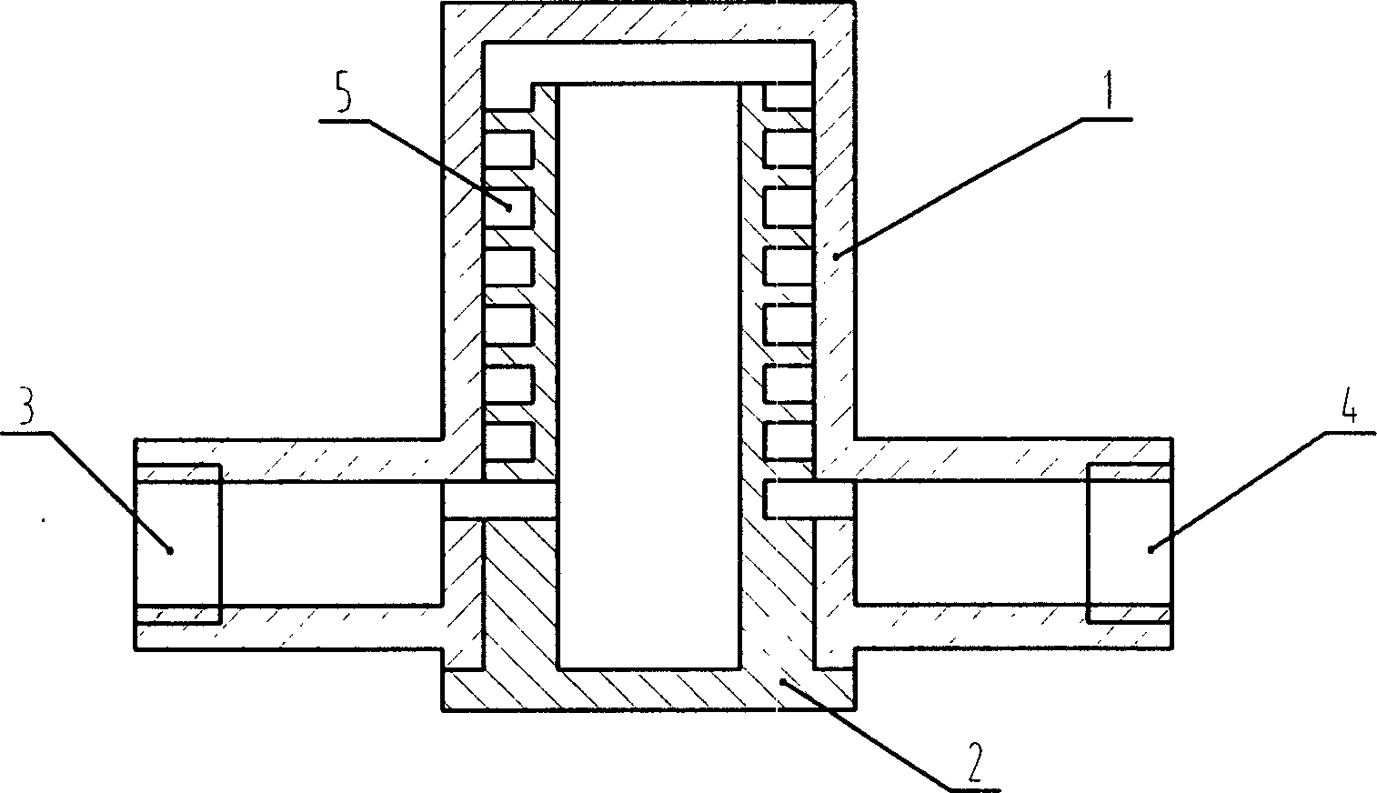
[0017] exist figure 1 Among them, the combination of the valve body (1) and the valve core (2) forms a helical tubular flow channel, in which the inlet (3) located at the lower part of the steam trap is connected to the inner cavity of the valve core (2) through the flow channel, and is located at the lower part of the steam trap. The outlet (4) on the other side is connected with the helical tube of the valve core (2), and the top of the inner cavity of the spool (2) is connected with the helical tube (5).

[0018] Steam condensate enters the valve body from the inlet (3), first enters the inner cavity of the valve core, enters the spiral tube from the top of the inner cavity, and flows into the outlet (4) from top to bottom. When the single-phase liquid steam condensate enters the steam trap, it can Flowing through the spiral tube smoothly, when steam is entrained in the condensed water, the fluid in the tube is vaporized due to the indirect heating of the steam to the spira...


PUM


Abstract

This invention is a spiratron steam drainer and its use in the steam pipe network. It can be used as common drainer and also as clotted water recycling device. The characteristics are: there is a the valve casing the valve core form a spiratron passage, the input port at the bottom of the drainer is connected with the chamber of the valve core through this passage, the output port at the other side of the bottom of the drainer is linked with the spiratron drainer, the top of the chamber is connected with the spiratron tube. This drainer has high liability and meets the requirement of maintaining-demission. It has wide range of charge changing, can save the power and power device consuming by the common clotted water recycling device and increase the recycling ratio of clotted water.

Description

technical field [0001] The invention relates to a valve, in particular to a spiral tube steam trap and its application in a steam pipe network. Background technique [0002] Most industrial and mining enterprises use steam as a heat source, and thermal equipment using steam as a heat source discharges a large amount of steam condensed water, which is not only a valuable soft water resource, but also contains a large amount of heat energy that can be used. The problem of condensate discharge and recovery has a great impact on the production environment, product quality and production cost of the enterprise. Since the current steam traps all work under zero back pressure, the condensed water can only be discharged to the sewer, resulting in a waste of a lot of soft water resources and heat. [0003] Even if condensate recovery is not considered, there are still big problems purely in terms of steam trap technology. Currently, there are few reliable steam traps on the market, ...

Claims


Application Information

Patent Timeline
Patent Type & Authority Applications(China)
IPC IPC(8): F16T1/00
Inventor 周根明陈育平周云祥顾晓波
Owner JIANGSU UNIV OF SCI & TECH
Why Eureka
Try Eureka