
Nozzle for use in hot runner mold

A hot runner and nozzle technology, applied in the field of injection nozzles, can solve the problems of high manufacturing cost and complex mold structure

Inactive Publication Date: 2005-03-16
HONDA MOTOR CO LTD
View PDF0 Cites 2 Cited by
  • Summary
  • Abstract
  • Description
  • Claims
  • Application Information

AI Technical Summary

Problems solved by technology

However, according to this structure, the mold must have a complicated structure
Such complex hot runner molds are very expensive to manufacture

Method used


Image

  • Nozzle for use in hot runner mold
  • Nozzle for use in hot runner mold
  • Nozzle for use in hot runner mold

Examples


Embodiment Construction

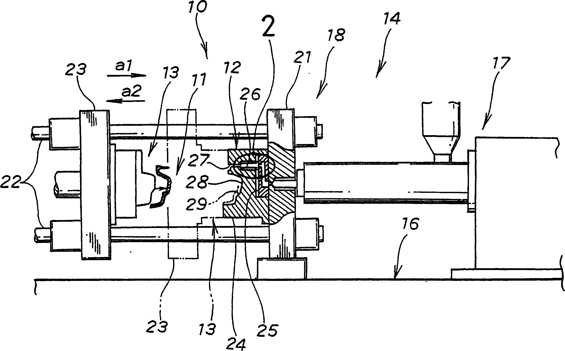
[0018] reference figure 1 , The hot runner mold 10 includes a fixed mold 12 and a movable mold 13 arranged to be engaged with the fixed mold 12. The mold 10 is installed in an injection molding machine 14 to manufacture a resin molded product 18.

[0019] The machine 14 includes: a support 16; an injection device 17 located on the support 16; and a mold clamping mechanism 18.

[0020] The mechanism 18 includes a fixed pressing plate 21, a connecting rod 22 mounted on the pressing plate 21, and a movable pressing plate 23 slidably mounted on the connecting rod 22. The movable pressing plate 23 is slidable in the direction indicated by the arrow a1, so that the movable mold 13 mounted on the pressing plate 23 is moved to the closed position shown by the two-dot chain line. In this closed position, the mold 13 is clamped to the fixed mold 12 by a predetermined pressure applied thereto. The movable platen 23 can also slide in the direction shown by the arrow a2, thereby moving the mo...


PUM


Abstract

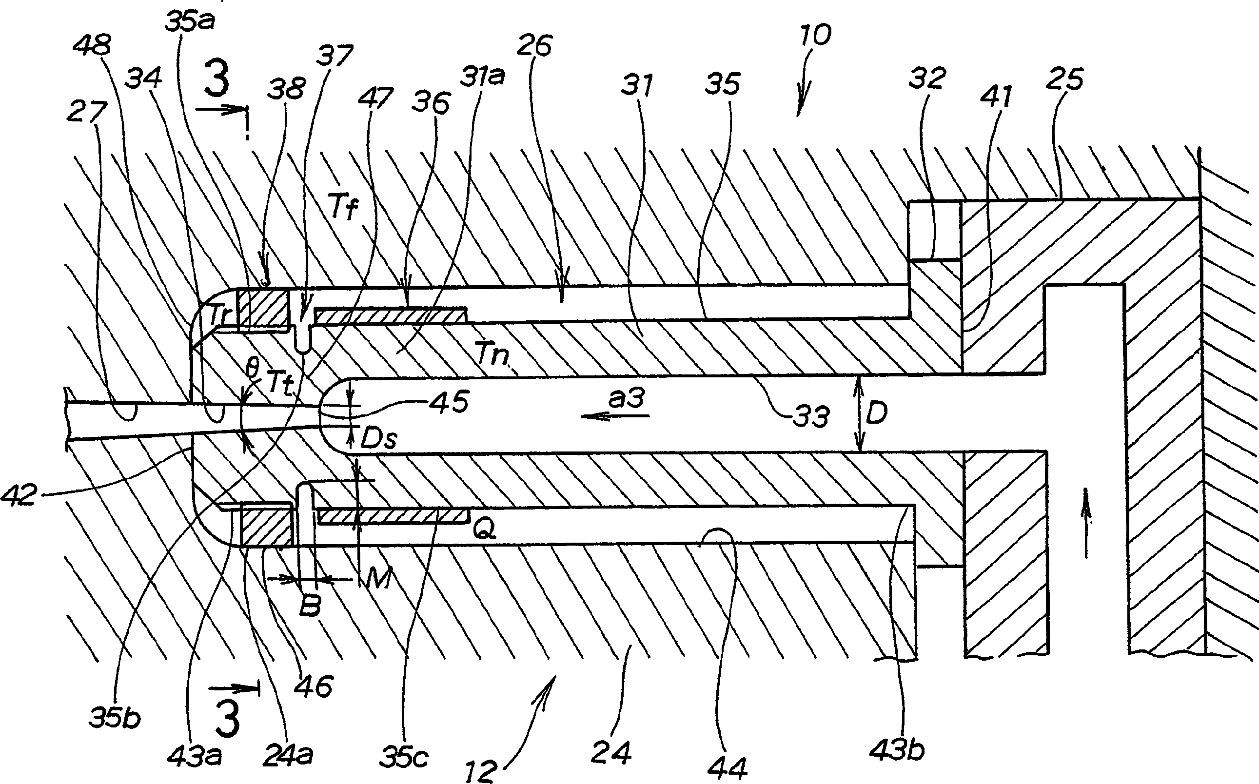
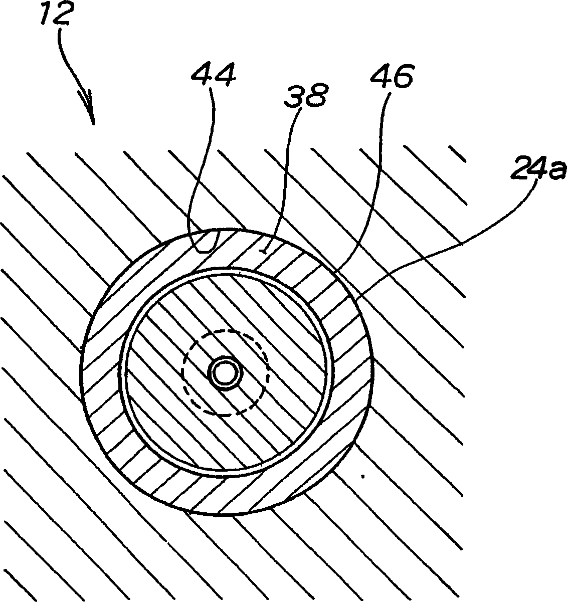
A nozzle (26) for a hot runner mold (10) having a cavity (29) and a runner (27) formed in a body (24) thereof and communicating with the cavity. The nozzle leads to the runner and has a heating means (36), a heat-insulating groove (37), and a heat transmitting ring (38) provided on an outer peripheral surface (35) thereof. The nozzle has a f low passageway (33) formed therein. The heating means, the groove, and the ring are arranged in order along a direction of flow of resin (51) within the passageway. The groove serves to prevent heat generated by the heating means from being transferred to a distal end portion (43a) of the nozzle. The ring serves to release the heat of the distal end portion to the body. With this arrangement, the resulting molded product (11) can be removed from the mold without causing any stringiness between the runner and the distal end portion.

Description

Technical field [0001] The present invention generally relates to a hot runner mold for manufacturing resin moldings, and more particularly to an injection nozzle provided in the hot runner mold. Background technique [0002] Fig. 5 shows a conventional hot runner mold 101, which has a nozzle body 102 disposed therein. The nozzle body 102 has flow channels 104 and 105, which are centered relative to the transverse direction of the nozzle body and formed to extend longitudinally. These flow passages 104 and 105 guide the molten resin 103 to pass therethrough. The nozzle body 102 has a heating device 107 installed around its outer circumferential surface 106. The heating device 107 maintains the resin 103 at a predetermined temperature and prevents the resin 103 from curing in the flow channel 104. [0003] However, for the runner mold 101 arranged in this way, when the molded product 108 is taken out from the mold 101, it can cause stringness in the molded product 108, as describe...

Claims


Application Information

Patent Timeline
Patent Type & Authority Applications(China)
IPC IPC(8): B29C45/27
CPCB29C2045/2724B29C2045/2777B29C45/27B29C45/20B29C45/72
Inventor 中野博英小山武小高光一
Owner HONDA MOTOR CO LTD
Learn More