Suction nozzle of vacuum cleaner

A technology of vacuum cleaners and suction pipes, applied in the direction of suction nozzles, etc., can solve problems such as difficulty in dust collection, achieve the effect of easy dust collection and improved work efficiency

Inactive Publication Date: 2005-03-30
LG ELECTRONICS (TIANJIN) APPLIANCES CO LTD
View PDF0 Cites 2 Cited by
  • Summary
  • Abstract
  • Description
  • Claims
  • Application Information

AI Technical Summary

Problems solved by technology

But in the prior art, because the lower end of the above-mentioned suction pipe 30 collides with the rear end of the above-mentioned suction nozzle 10, the above-mentioned suction pipe 30 cannot swim to the bottom according to a certain angle, which brings difficulties to the dust collection in a relatively narrow space. difficulty

Method used


Image

  • Suction nozzle of vacuum cleaner
  • Suction nozzle of vacuum cleaner
  • Suction nozzle of vacuum cleaner

Examples


Embodiment Construction

[0052] Embodiments of the suction nozzle of the vacuum cleaner of the present invention will be described in detail below with reference to the accompanying drawings.

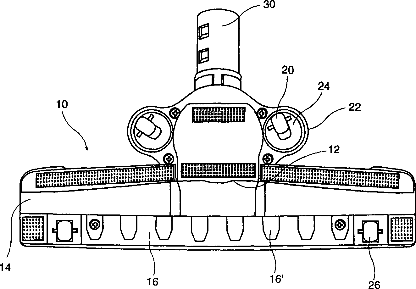
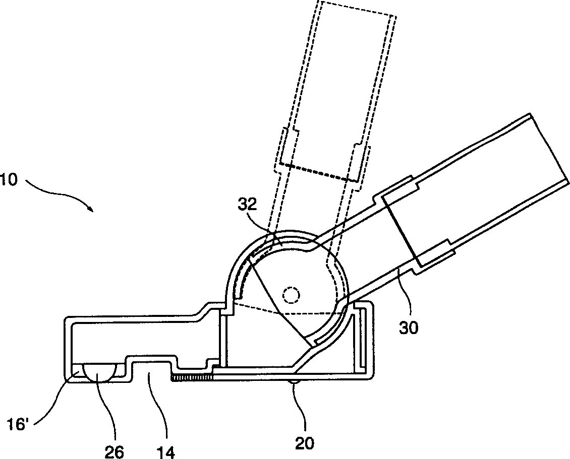
[0053] Figure 4 A perspective view showing a nozzle of a vacuum cleaner according to an embodiment of the present invention. Figure 5 A bottom view showing a nozzle of a vacuum cleaner according to an embodiment of the present invention. Image 6 It is an exploded oblique view showing the structure of the suction nozzle of the vacuum cleaner according to the embodiment of the present invention. Figure 7 It is an exploded perspective view of the bottom surface of the flow-path connecting member showing the structure of the main part of the nozzle of the vacuum cleaner of the present invention. Figure 8 A side sectional view showing the structure of a suction nozzle of a vacuum cleaner according to an embodiment of the present invention.

[0054] As shown in the figure, the appearance of the suction nozzle...


PUM


Abstract

A sucking mouth of vacuum cleaner is composed of a lower case to form the bottom surface of sucking mouth, an upper case playing the appearance role, and a sucking pipe connected to the extended pipe of vacuum cleaner.

Description

technical field [0001] The present invention relates to a vacuum cleaner; furthermore, it relates to a suction nozzle (INDUCTION NOZZLE ASSEMBLY FORVACUUM CLEANER) of a vacuum cleaner in which a recess is formed at the lower end of a suction pipe. Background technique [0002] Generally speaking, a vacuum cleaner is a device that generates strong suction in the body of the vacuum cleaner, and forcibly sucks the dust on the ground through the suction nozzle to perform dust collection. Vacuum cleaners are widely used in general households recently and become an indispensable appliance for cleaning carpets or sofas. [0003] figure 1 An oblique view showing a typical prior art vacuum cleaner. [0004] Such as figure 1 As shown, a general vacuum cleaner includes the following structure: a body 2 , a connecting hose (HOSE) 4 , an extension pipe 6 and a suction nozzle 10 . [0005] The inside of the above-mentioned body 2 is provided with a motor for generating suction; the ab...

Claims


Application Information

Patent Timeline
IPC IPC(8): A47L9/02
Inventor 金庆出郑在德
Owner LG ELECTRONICS (TIANJIN) APPLIANCES CO LTD
Why Eureka
Try Eureka