Power lumbar mechanism

A driving mechanism, waist technology, applied in vehicle parts, movable seats, transportation and packaging, etc., can solve problems such as linear offset that cannot meet the screw thread size and time, and difficulty in providing power from a central vortex tube.

Inactive Publication Date: 2005-03-30
L & P PROPERTY MANAGEMENT CO
View PDF3 Cites 19 Cited by
  • Summary
  • Abstract
  • Description
  • Claims
  • Application Information

AI Technical Summary

Problems solved by technology

Since the screw is preferably made of molded plastic material, small threads cannot withstand the forces acting on plastic threads, nor can it satisfy the need to simply change the thread size of the screw to reduce linear shift over time
Finally, as designed, it is difficult to power the center scroll since the counter scroll tends to rotate relative to the screw and torque applied to the scroll also causes motion in the opposite direction

Method used


Image

  • Power lumbar mechanism
  • Power lumbar mechanism
  • Power lumbar mechanism

Examples


Embodiment Construction

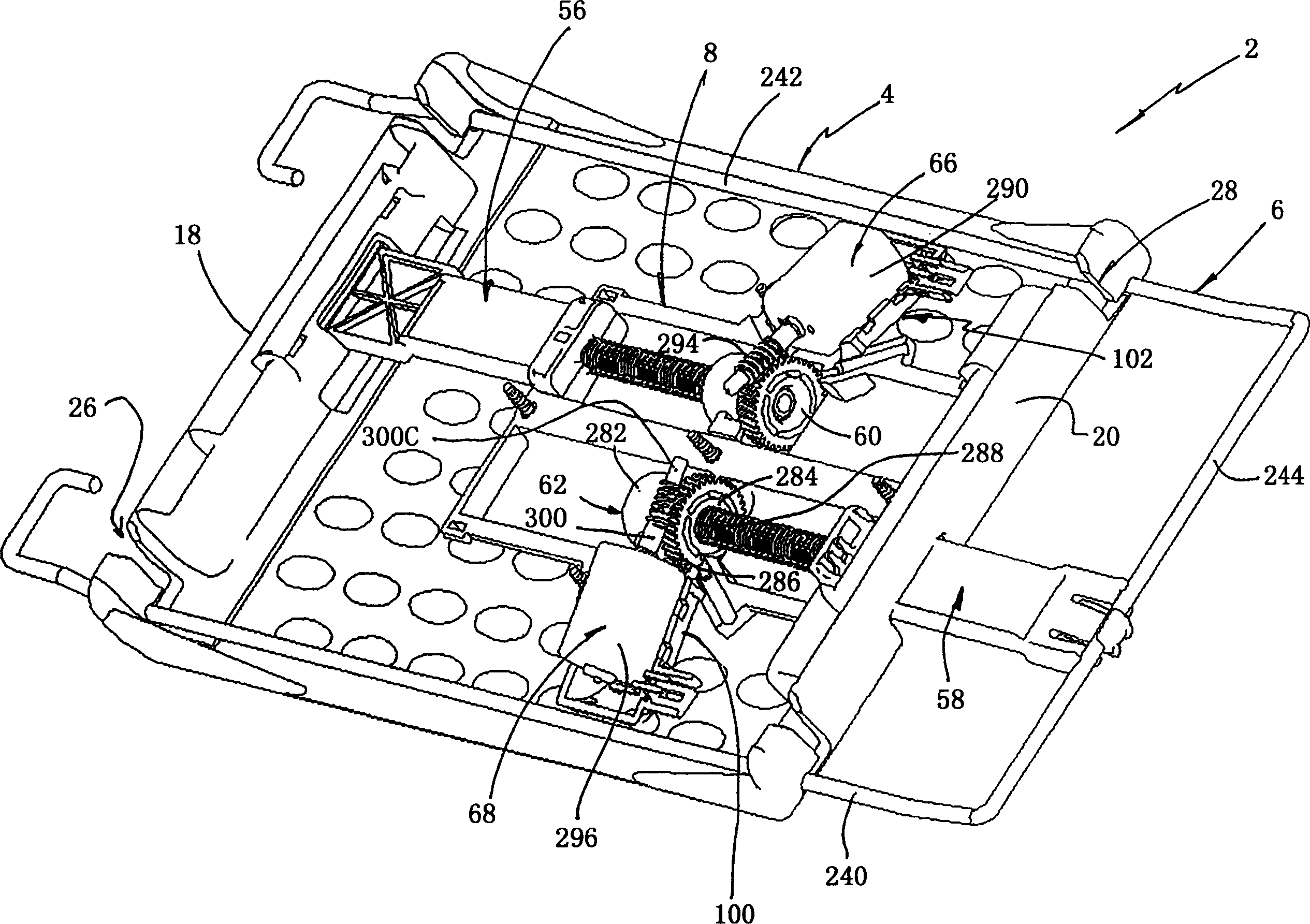
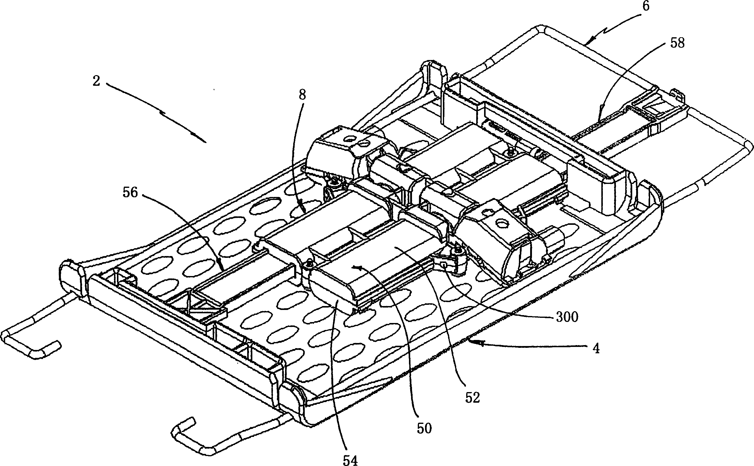
[0034] First refer to figure 1 and 2, the power lumbar mechanism is generally indicated by reference numeral 2, which includes a curved plate 4, which is slidably connected with the support structure 6 in the backrest of the seat, and the driving mechanism 8 attached to the lumbar mechanism is used to change the curved plate 4 The curvature and the position of the plate 4 relative to the support structure 6.

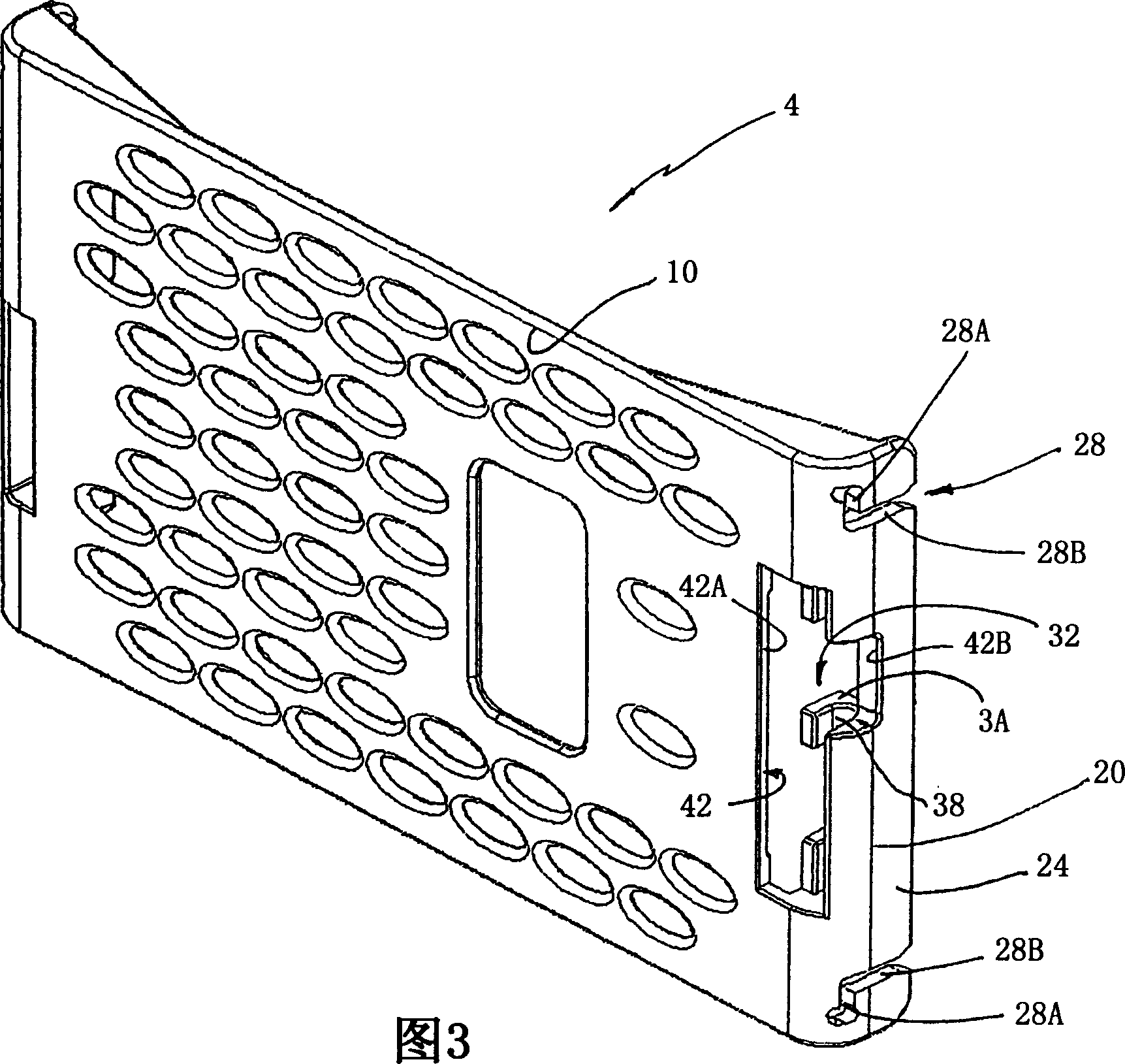
[0035] The curved plate, which includes an outer contact surface 10, an inner surface 12, sides 14, 16, and end edges 18, 20, will now be described in further detail with reference to FIGS. End edges 18 , 20 include straight sides 22 , 24 each of which includes an L-shaped groove 26 , 28 . These L-shaped slots include horizontal slot sections 26A, 28A and vertically extending slot sections 26B, 28B. Each end 18, 20 further includes a trunnion portion 30, 32, wherein each trunnion includes a slotted portion 34, 36 and a channel portion 38, 40, which will be further des...


PUM


Abstract

A powered lumbard support mechanism (2) includes a lumbar plate (4) having a power mechanism connected to opposite ends of the plate. The mechanisme comprises a movable link (56) connected to one end of the plate which is longitudinally movable to change the convexity of the outer surface of the plate to adjust the lumbar support. The power mechanism includes a housing (50) which retains a threaded rod (254) of the movable link threaded into a worm gear mechanism (60) held within the housing. The housing also retains a motor (66) having a worm which drives the threaded worm gear (60). The housing can also incorporate a second movable link (58) with a threaded rod (264), threaded to a second threaded worm gear (62) also fixed within the housing (50) such that the end of the second threaded rod is connected to a horizontal seat support (244) so as to allow for the adjustability of the vertical position of the lumbar mechanism.

Description

[0001] This application claims the benefit of US Provisional Patent Applications Serial Nos. 60 / 343073, filed December 19, 2001, and 60 / 32856, filed October 11, 2001, the entire disclosures of which are hereby expressly incorporated by reference. technical field [0002] The present invention relates to a powered lumbar support system for a seat back wherein both the convexity and position of the lumbar support within the seat can be adjusted. Background technique [0003] Both manual and motorized versions offer many different kinds of waist contouring mechanisms. One such manual type is shown in US Patent 5775773, which discloses a plurality of horizontally extending waist members attached to a vertical support mechanism placed laterally, wherein the vertical support mechanism can be bent from the top by connecting with Bowden cables To the bottom, the cable changes the convexity of the lumbar mechanism when shortened. When the lumbar mechanism is located in the seat back...

Claims


Application Information

Patent Timeline
Patent Type & Authority Applications(China)
IPC IPC(8): A47C7/46B60N2/02B60N2/66
CPCB60N2/0232A47C7/465B60N2/66B60N2/666B60N2/6673B60N2/02246
Inventor J·R·范西克立
Owner L & P PROPERTY MANAGEMENT CO
Why Eureka
Try Eureka