Digital sensor for miniature medical thermometer, and body temperature monitor

A sensor device, digital technology, applied in thermometer parts, sensors, thermometers, etc., can solve the problems of signal interference and indistinguishable

Inactive Publication Date: 2005-04-06
MINI MITTER
View PDF7 Cites 3 Cited by
  • Summary
  • Abstract
  • Description
  • Claims
  • Application Information

AI Technical Summary

Problems solved by technology

[0008] However, these devices have severe application limitations because they are purely analog devices, transmitting continuously on a single frequency
This prevents the use of multiple devices on a single subject or on subjects in close proximity to each other because the signals from the independent devices interfere with each other and cannot be distinguished

Method used


Image

  • Digital sensor for miniature medical thermometer, and body temperature monitor
  • Digital sensor for miniature medical thermometer, and body temperature monitor
  • Digital sensor for miniature medical thermometer, and body temperature monitor

Examples


Embodiment Construction

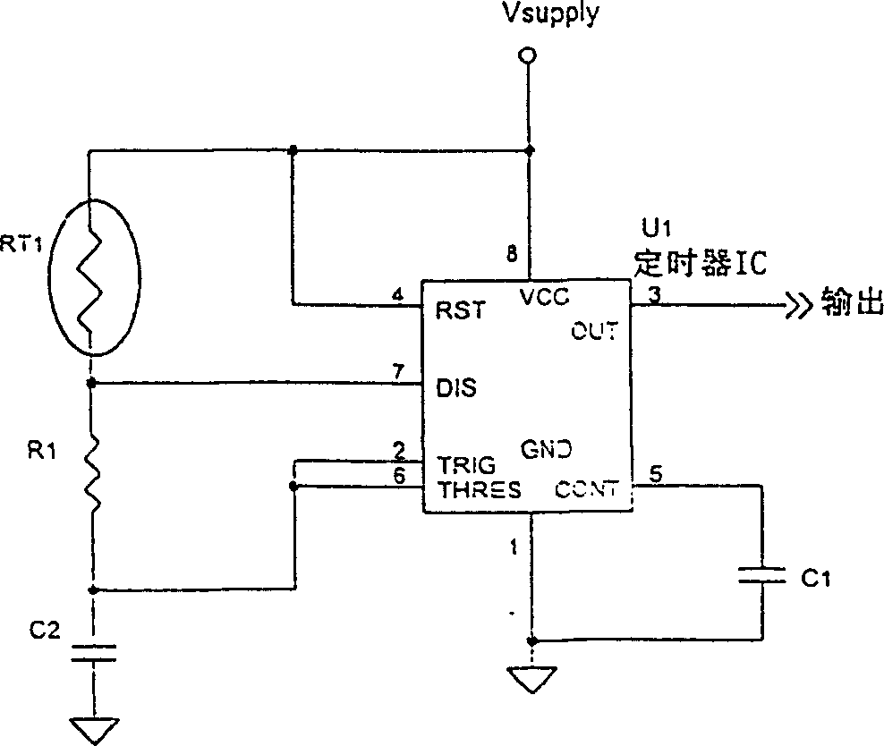
[0040] exist figure 1 The temperature sensitive circuit shown is a classic 555 timing circuit whose charging time is controlled by resistor R T and R 1 and capacitor C2 is controlled, and its discharge time is controlled by the resistor R 1 and the capacitor C2 controls that. The classic 555 timing circuit uses an external network to control the frequency, and the 555 timer is well known for its various uses in converters.

[0041] In one embodiment of the present invention, R T is a precision thermistor with approximately 100kohm resistance at 25°C, and R 1 is a 100kohm precision fixed resistor. This will generate a 555 pulse waveform whose charging time is t c Approximate discharge time t d twice as much as figure 2 shown.

[0042] When the temperature increases above 25°C, the thermistor resistance will decrease because the thermistor has a negative temperature coefficient. Signal waveforms generated at temperatures above 25°C will have a reduced duty factor and ...


PUM


Abstract

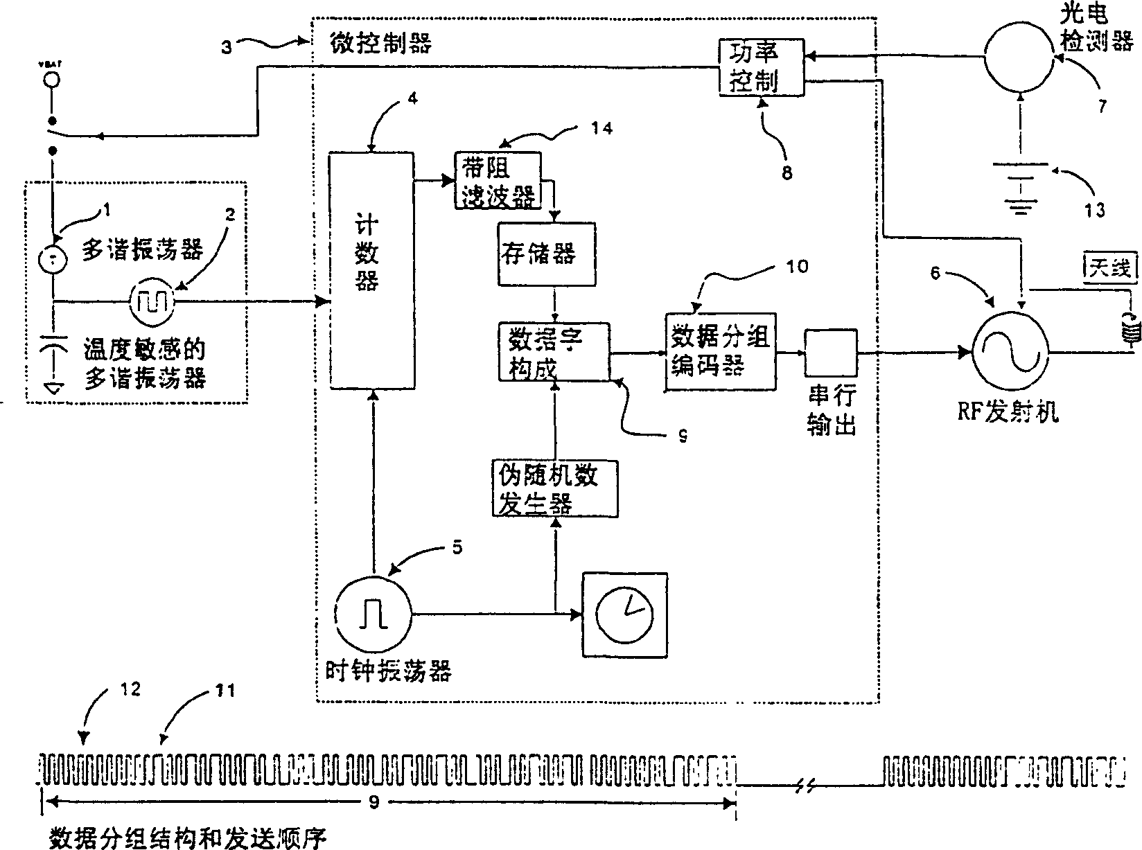
A thermometer is disclosed that utilizes a thermistor as a temperature sensor, to control the period and duty cycle of a multivibrator circuit. A second circuit, controlled by a microcontroller, measures both the charge and discharges times of the oscillation. From the ratio of these parameters, a precise indication of temperature can be obtained that is independent of temperature variations within the active components and the charging capacitor of the multivibrator circuit. The method is also independent of the value of the charging capacitor. Furthermore, by measuring the same ratio when a fixed resistor is substituted for the thermistor, a cell constant can be derived. The cell constant is used to calibrate the non-ideal response of the multivibrator circuit, thus providing a more accurate measurement of temperature.

Description

[0001] This application is based on a divisional application with an international application date of December 12, 2001, an application number of 01820417.1, and an international application number of PCT / US01 / 48358, and the title of the invention is "Digital Sensor and Body Temperature Monitor for Micro Medical Thermometers" . technical field [0002] In a first aspect, the invention relates to an electronic thermometer, and more particularly, though not exclusively, to a thermometer useful for measuring body temperature of a human or animal subject, or for measuring ambient temperature. In a second aspect, the invention relates to a telemetry system consisting of a transmitting measuring device, preferably a body temperature thermometer, and a portable receiving unit displaying the measured value of a sensed parameter. This application claims priority to Provisional Application No. 60 / 254,879, filed December 12,2000. Background technique [0003] Several prior art invent...

Claims


Application Information

Patent Timeline
Patent Type & Authority Applications(China)
IPC IPC(8): G01K1/02A61B5/01G01K7/24G01K7/25G08C19/00G08C23/04
CPCG01K7/245
Inventor F·G·贝尔D·K·巴顿J·S·莱尔德C·T·琼斯
Owner MINI MITTER
Why Eureka
Try Eureka