
Automatic gear shifting mechanism for vehicle

An automatic transmission and operating device technology, applied in the direction of transmission control, control devices, vehicle components, etc., can solve the problems of wire rack installation position restrictions, loud operation sound, and durability deterioration, so as to avoid durability deterioration and reduce Small operation sound, effect of reducing width size

Active Publication Date: 2005-04-20
ATSUMITEC CO LTD
View PDF1 Cites 1 Cited by
  • Summary
  • Abstract
  • Description
  • Claims
  • Application Information

AI Technical Summary

Problems solved by technology

[0007] However, in the above-mentioned conventional automatic transmission operating device for vehicles, when the shift lever is operated to tilt from the automatic mode to the manual mode, the operating sound becomes louder due to the sliding between the shift lever and the bracket or the cover plate. , the problem of rapid deterioration of durability due to wear due to sliding resistance
In addition, it is necessary to provide a door slot or a part of the bracket that slides relative to a part of the shift lever.
There is a problem that the applicable form of the automatic transmission operating device with two modes of automatic mode and manual mode is limited
[0008] In addition, as the bulletin Figure 7 As shown, in the structure in which the vicinity of one end of the pivot shaft is inserted through the cylindrical portion formed in the wire stand, the width direction dimension of the swing and tilt mechanism becomes large due to the lengthwise dimension of the pivot shaft and the thickness dimension of the wire stand. , causing the overall device to become larger
And, as the communiqué Figure 11 As shown, in the double structure in which the pivot covers the cylindrical portion extending from the thread stand, it is necessary to form a cutout for avoiding interference with the thread stand on the pivot, so the installation position of the thread stand is limited, and the design is free. small size problem

Method used


Image

  • Automatic gear shifting mechanism for vehicle
  • Automatic gear shifting mechanism for vehicle
  • Automatic gear shifting mechanism for vehicle

Examples


Embodiment Construction

[0033] Hereinafter, embodiments of the present invention will be specifically described with reference to the drawings.

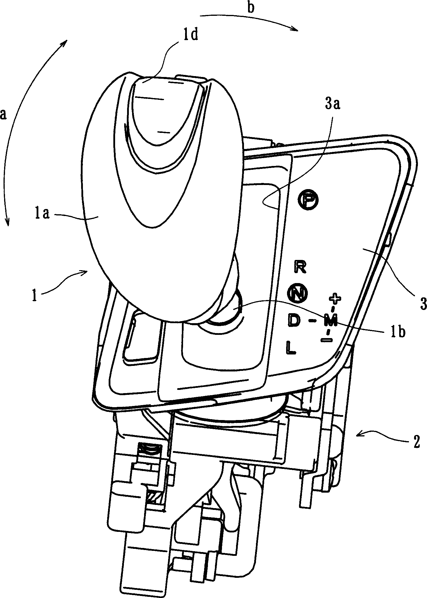
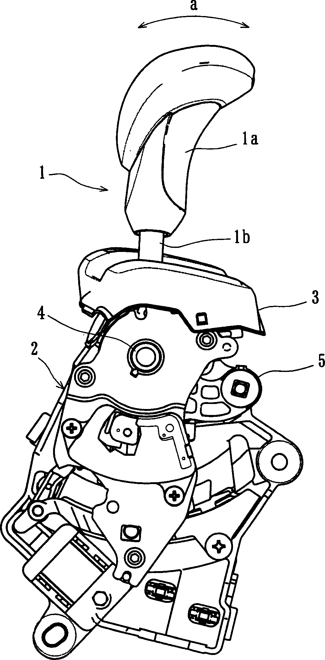
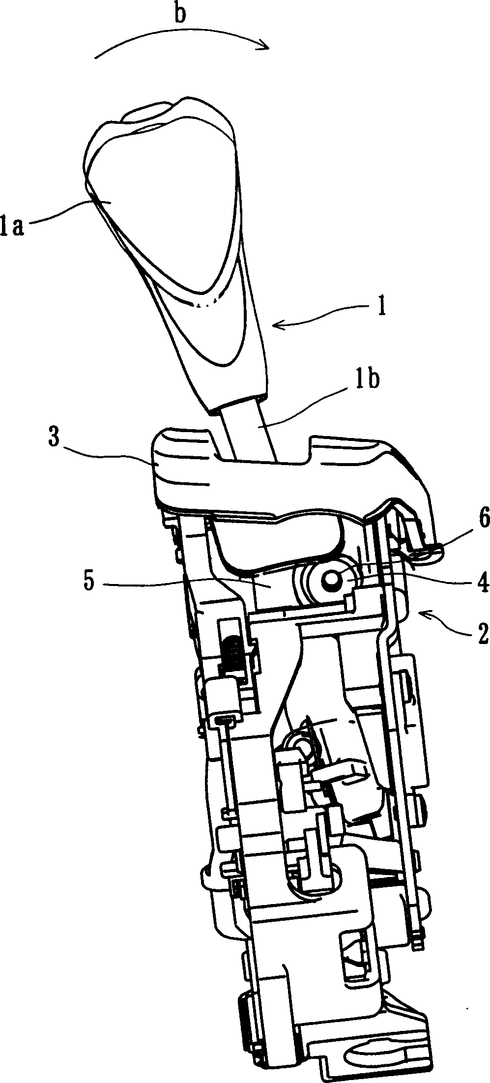
[0034] The automatic transmission operating device for vehicles involved in this embodiment can arbitrarily set the automatic mode and the manual mode, such as Figure 1 ~ Figure 3 As shown, in appearance, it is mainly composed of a shift lever 1, a bracket 2 fixed on the vehicle body, and a cover plate 3 covering the surface of the bracket 2, wherein the shift lever 1 is mainly composed of a handle part 1a and a rod part 1b .

[0035]The shift lever 1 is supported so that components such as the bracket 2 and the cover plate 3 fixed on the vehicle body relative to the cover plate can swing to the front and rear direction (a direction in the figure) of the vehicle body, and can swing to the left and right direction (b direction in the figure). direction) to pour, so in the normal state, the automatic mode is formed by shaking in the forward and backward dir...


PUM


Abstract

Provided is an automatic shifting operation device for a vehicle, which can reduce the operation sound when the shift lever is tilted from the automatic mode to the manual mode, avoid deterioration of durability due to wear, and expand the applicable form at the same time. The automatic transmission operating device for vehicles has a shift lever (1) that is supported so as to be able to swing forward and backward relative to the bracket (2) and tilt to the left and right directions, and has: a pivot shaft (4) to make the shift lever (1) It can swing forward and backward, and is formed with an opening (K2) that can be inserted through the shift lever (1); the support pin (6) is arranged in the opening (K2) of the pivot (4), so that the shift lever (1) The relative bracket (2) can be tilted to the left and right; the protrusion (7) and the recess (11) contact the shift lever (1) that is tilted around the support pin (6) to limit its tilting range, These parts are all arranged in the opening (K2) of the pivot (4).

Description

technical field [0001] The present invention relates to an automatic transmission operating device for a vehicle which can set an automatic mode and a manual mode arbitrarily. Background technique [0002] The automatic transmission operating device of an automobile is configured such that a shift lever protrudes from a bracket fixed to a vehicle body, and a desired operation of an automatic transmission of an automobile can be performed by swinging the shift lever forward and backward. Also, in such an automatic transmission operating device, when the shift lever is in the forward range (D range), the shift lever can be tilted leftward or rightward, and the transmission can be manually operated from this state to the rearward direction. [0003] For example, as disclosed in Patent Document 1, during normal automatic transmission operation (automatic mode), the automatic transmission can be placed in the park position (P) by swinging the shift lever in the forward and rearwa...

Claims


Application Information

Patent Timeline
IPC IPC(8): B60K20/04F16H59/02
Inventor 小田繁朗新村雅之小池久仁博
Owner ATSUMITEC CO LTD
Learn More