Sealing Structure

一种密封结构、邻接的技术,应用在发动机的密封、发动机的密封装置、发动机元件等方向,能够解决液态填料不能令人满意固化等问题

Active Publication Date: 2005-04-20
NISSAN MOTOR CO LTD
View PDF1 Cites 7 Cited by
  • Summary
  • Abstract
  • Description
  • Claims
  • Application Information

AI Technical Summary

Problems solved by technology

Therefore, the liquid filler in the storage portion sometimes does not solidify satisfactorily even after a predetermined drying time elapses

Method used


Image

  • Sealing Structure
  • Sealing Structure
  • Sealing Structure

Examples


Embodiment Construction

[0020] Selected embodiments of the present invention will now be explained with reference to the drawings. Those skilled in the art can easily understand that: the following descriptions of the embodiments of the present invention are only for explaining the present invention, and cannot be used to limit the present invention as defined in the claims.

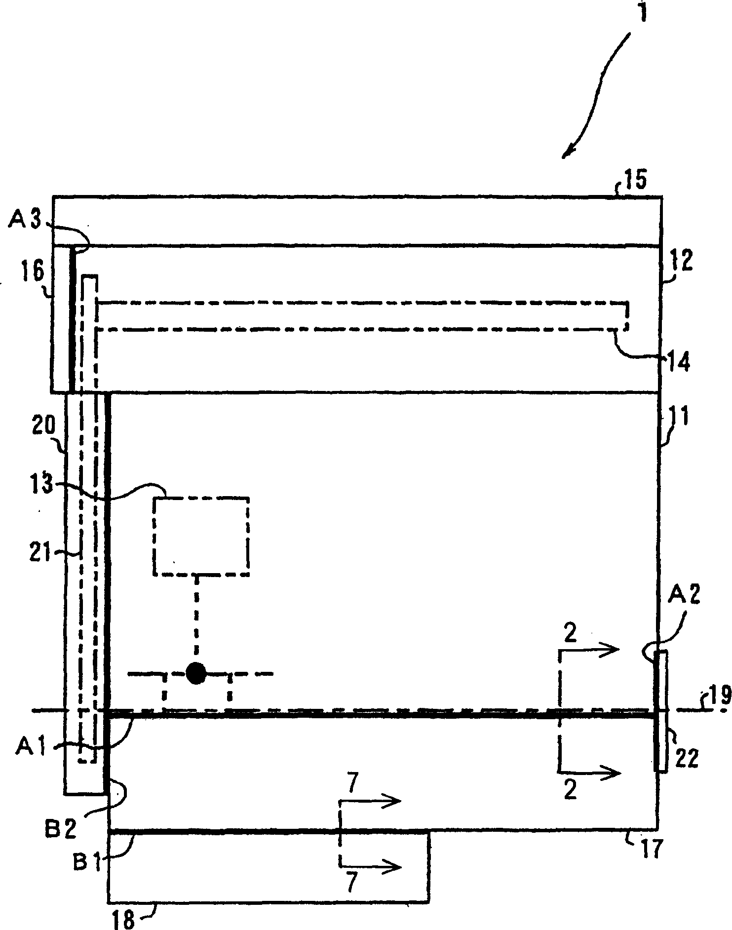
[0021] first reference figure 1 , which shows a sealing structure according to a preferred embodiment of the present invention. In the following description, the sealing structure according to the present invention refers to a "slope sealing structure".

[0022] figure 1 is a schematic diagram of an engine 1 used in a locomotive using the inclined plane sealing structure according to the first embodiment of the present invention. figure 1 The left side of is the front side of the engine 1, and the right side is the rear side of the engine 1.

[0023] Such as figure 1 As shown, the main body of the engine 1 includes a cylin...


PUM


Abstract

An upper oil pan (17) of an engine (1) includes a flange (171) with an oil pan abutment surface (172) that is fixedly coupled to a flange (111) formed on a cylinder block (11). The oil pan abutment surface (172) comprises a flat portion (1721) that is substantially parallel to a cylinder block abutment surface (112) of the cylinder block (11), a slanted portion (1722) that is slanted with respect to the flat portion (1721), and a vertical wall portion (1723) connecting the flat portion (1721) and the slanted portion (1722). The vertical wall portion (1723) is formed substantially perpendicular to the flat portion (1721). The cylinder block (11) and the upper oil pan (17) are fixedly coupled together via an interposed liquid gasket (31a). Thus, the seal structure in which the liquid gasket (31a) is adequately cured is provided, and sufficient sealing properties can be obtained with a small amount of material used. <IMAGE>

Description

technical field [0001] The invention relates to a sealing structure. In particular, it relates to a liquid packing sealing structure suitable for use in an oil seal between a cylinder block and an upper oil pan and / or an upper oil pan and a lower oil pan or the like in an engine. Background technique [0002] An example of a conventional liquid packing seal structure is disclosed in Japanese Patent Application Publication No. H11-173424, which employs a form-in-place packing for an engine oil seal structure. Specifically, in such a conventional liquid packing seal structure, a groove is provided near the center of the flange abutment surface on either of two members joined together by forming in situ (form -in-place) filler is a liquid filler connected together. When the two components are joined, the groove acts as a reservoir for the liquid charge. Especially when assembling an engine, a liquid filler is applied to the adjoining surface of a flange of one of the two par...

Claims


Application Information

Patent Timeline
Patent Type & Authority Applications(China)
IPC IPC(8): F01M11/00F02F11/00F16J15/06F16J15/14
CPCF02F11/00F01M2011/0062F16J15/062F16J15/14
Inventor 田口新近藤美登理羽田雅敏
Owner NISSAN MOTOR CO LTD
Why Eureka
Try Eureka