Superfine pipeline heat exchanger

A heat exchanger and pipeline technology, applied in the field of branch pipe structure, can solve the problems of poor heat exchange performance, large flow resistance, and ineffective heat exchange between flowing air and heat sink 6, so as to reduce air pressure loss and prevent heat conduction. volume reduction effect

Inactive Publication Date: 2005-05-04
LG ELECTRONICS (TIANJIN) APPLIANCES CO LTD
View PDF0 Cites 1 Cited by
  • Summary
  • Abstract
  • Description
  • Claims
  • Application Information

AI Technical Summary

Problems solved by technology

However, the flowing air flowing through the cooling fins 6 near the lower header 1 will be subjected to a particularly large flow resistance, because condensed water flows down from the upper part around the cooling fins 6 near the lower header 1 and gathers and stagnates in the Therefore, there will be a large flow resistance
In this case, there is a problem that heat exchange between the flowing air and the cooling fins 6 cannot be effectively performed due to an increase in flow resistance, thereby deteriorating heat exchange performance.

Method used


Image

  • Superfine pipeline heat exchanger
  • Superfine pipeline heat exchanger
  • Superfine pipeline heat exchanger

Examples


Embodiment Construction

[0029] Embodiments of the ultra-fine tube heat exchanger of the present invention will be described in more detail below with reference to the accompanying drawings.

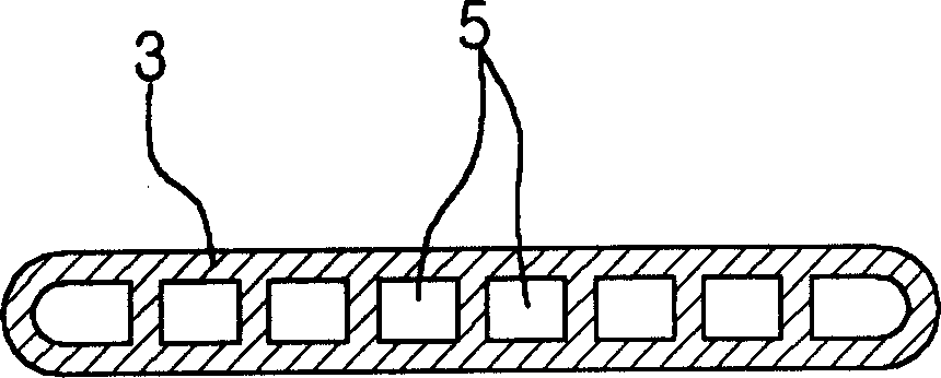
[0030] Figure 5a It is a side view of the state in which several cooling fins are installed on the branch pipe in the present invention; Figure 5b is a cross-sectional view of a branch pipe of the present invention; Figure 6 It is a view of the discharge condition of condensed water in the present invention.

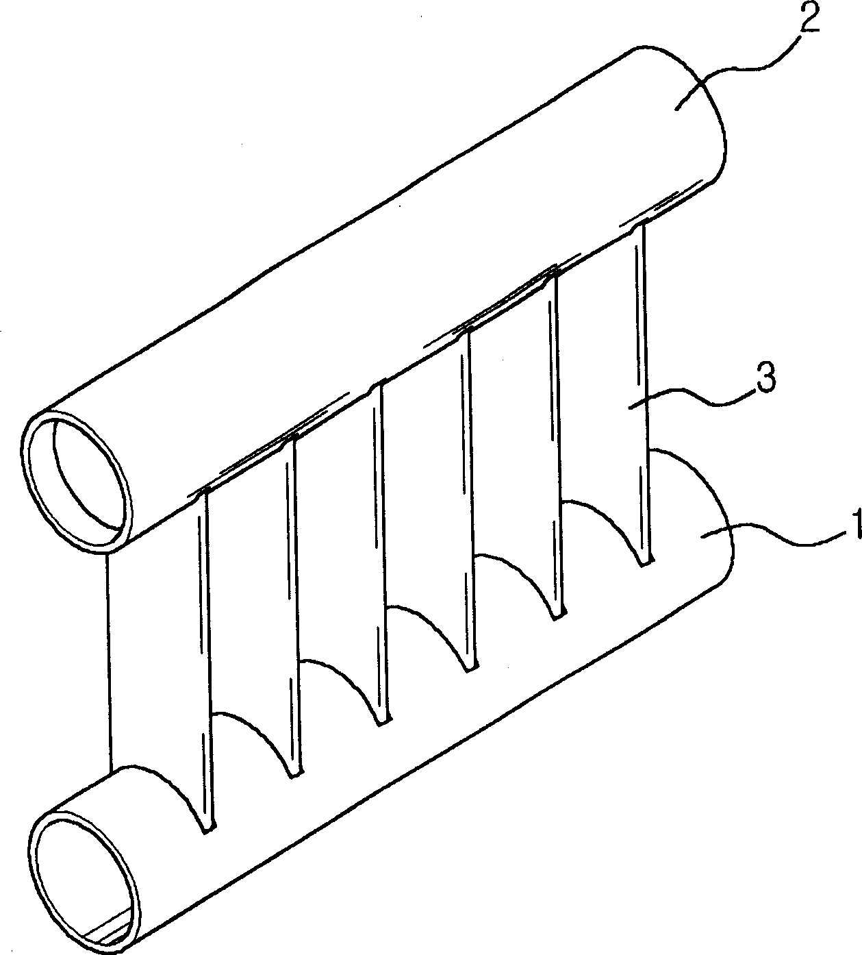
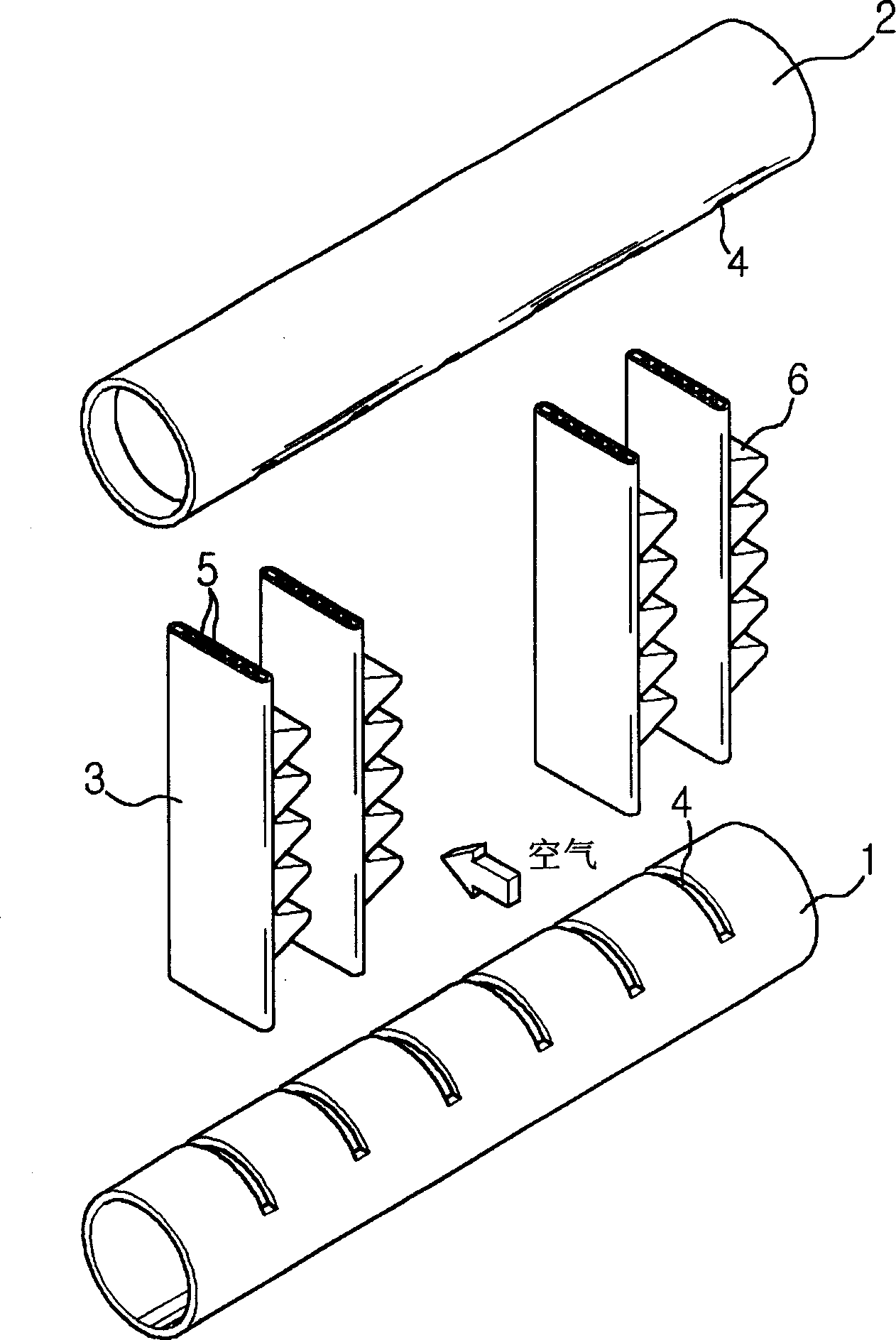
[0031] With reference to the accompanying drawings, it can be known that, unlike the prior art structure in which only a single cooling fin is installed on the branch pipe 3, in the present invention, several cooling fins 6a, 6b are installed on the branch pipe 3 at certain intervals. , 6c. The condensed water generated on the surface of each cooling fin will flow down along the direction of gravity, and the condensed water 7 will gather at the lowermost end of each cooling fin, and then under the fo...


PUM


Abstract

This invention relates to a kind of arrangement structure of cooling fin that can smoothly discharge condensed water that condense on the surface of the cooling fin. The feature of the superthin tube heat-exchanger is that hollow level header can make refrigerant flow through; several refrigerant tubes insert in the level header, so it can distribute the refrigerant that flow in the level header; cooling fin that set between the vertical refrigerant tubes said above. In this heat exchanger, several cooling fins are fixed between the above vertical refrigerant tubes with a certain distance. This invention can discharge the condensed water flow from top of the refrigerant tube more easy. This invention can achieve another effect that it can reduce the air pressure losing of the flowing air on the effect of the fan, and prevent the heat reducing.

Description

technical field [0001] The invention relates to a branch pipe structure of a micro channel heat exchanger (Micro Channel HeatExchanger), which can smoothly discharge condensed water condensed on the surface of a cooling fin. Background technique [0002] figure 1 is a side view of the appearance of the heat exchanger, figure 2 It is an exploded view of each component structure of the heat exchanger, image 3 for figure 2 Sectional view of the branch pipe in . [0003] Referring to the above drawings, it can be seen that the existing heat exchanger is composed of the following parts, namely: the upper header 2 located above the corresponding lower header 1; Several branch pipes 3; cooling fins 6 formed between the above branch pipes 3. Generally speaking, in order to improve the heat exchange efficiency, plate-shaped cooling fins are installed on the outer surface of the branch pipe of the heat exchanger through which the refrigerator flows, and the heat exchange can b...

Claims


Application Information

Patent Timeline
Patent Type & Authority Applications(China)
IPC IPC(8): F24F13/22F24F13/30F28D1/02
Inventor 吴世基吴世允高喆洙史容澈长东延
Owner LG ELECTRONICS (TIANJIN) APPLIANCES CO LTD
Why Eureka
Try Eureka