Communications antenna system and mobile transmit and receive reflector antenna

A reflector antenna, the technology of the main reflector, applied in the direction of antenna, antenna suitable for movable objects, electrical components, etc.

Inactive Publication Date: 2005-05-04
THE BOEING CO
View PDF0 Cites 9 Cited by
  • Summary
  • Abstract
  • Description
  • Claims
  • Application Information

AI Technical Summary

Problems solved by technology

[0004] Another consideration for reflector antennas like ...

Method used


Image

  • Communications antenna system and mobile transmit and receive reflector antenna
  • Communications antenna system and mobile transmit and receive reflector antenna

Examples


Embodiment Construction

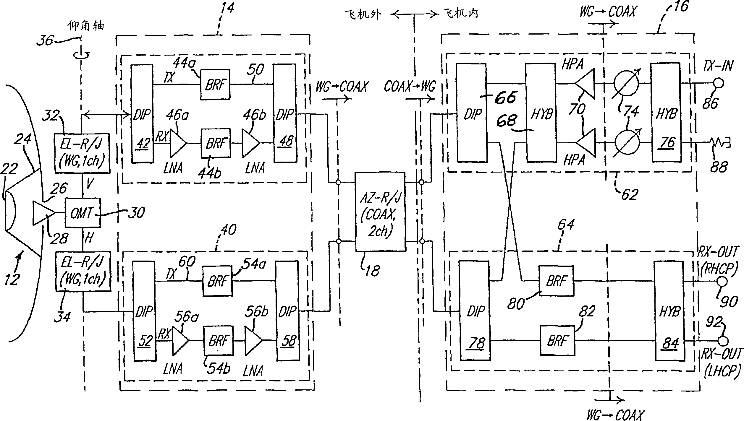
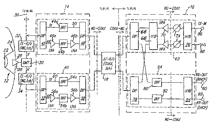
[0011] Refer to attached figure 1 , shows an antenna system 10 according to a preferred embodiment of the present invention. The antenna system 10 generally includes an antenna aperture 12, a first antenna signal processing subsystem 14, a second antenna signal processing subsystem 16, and a suitable rotary joint 18 to facilitate communication between the first and second subsystems 14 and 16, respectively. two-way communication.

[0012] The antenna aperture 12 includes a main reflector 20 , a sub-reflector 22 and an opening 26 centered on the axis of the main reflector 20 , wherein the sub-reflector 22 is supported forward of the main reflector 20 by a support structure 24 . Disposed within opening 26 is a feed horn 28 . In a preferred form, the length of the feed horn 28 is preferably 70 mm. However, the structure of the primary reflector 20 and sub-reflector 22 including pre-existing components does not allow for a feed horn of this length. This problem is solved by pl...


PUM


Abstract

A reflector antenna adapted for use with a mobile platform, in particular with an aircraft. The reflector antenna includes an antenna aperture, a first signal processing subsystem located closely adjacent the antenna aperture exteriorly of the mobile platform, a two channel coaxial rotary joint for allowing rotation of the antenna aperture about an azimuthal axis, and a second antenna signal processing subsystem located within the interior of the mobile platform. A feedhorn of the antenna aperture is disposed within an opening at a coaxial center of a main reflector to allow a longer length feedhorn to be employed without physically interfering with a subreflector of the antenna aperture. The first antenna signal processing subsystem includes separate channels for processing vertically polarized RF energy and horizontally polarized RF energy. The second antenna signal processing subsystem includes a transmit subsystem for amplifying and phase shifting transmit signals being sent to the antenna aperture for transmission, and a receive subsystem for processing received RF signals to provide right hand circularly polarized and left hand circularly polarized signals.

Description

technical field [0001] The present invention relates to antenna systems, and more particularly to a reflector antenna suitable for placement on the outer surface of a mobile platform such as an aircraft, and the reflector antenna includes a reflector antenna located on the outer surface of the mobile platform Certain signal processing components in close proximity to the antenna aperture and certain signal processing components placed inside the mobile platform. Background technique [0002] Antenna systems are used in a variety of applications. An increasingly important application is in connection with satellite-linked communication systems to provide Internet connectivity to mobile platforms such as aircraft. In such applications, when an antenna system placed on an aircraft is mounted to the outer surface of the aircraft fuselage, it must appear as an object of small height and width so that the antenna system does not contribute to the aerodynamic properties of the air...

Claims


Application Information

Patent Timeline
IPC IPC(8): H01Q1/28H01Q3/08H01Q19/19
CPCH01Q1/28H01Q3/08H01Q19/19
Inventor 艾伯特·L·比恩格伦·J·德萨甘特
Owner THE BOEING CO
Why Eureka
Try Eureka