Eureka AIR delivers breakthrough ideas for toughest innovation challenges, trusted by R&D personnel around the world.

Airplane stall recovery device

An aircraft and fuselage technology, applied in the field of stall recovery devices, can solve the problems of increasing the weight of the tail structure of the aircraft and affecting the aerodynamic performance of the aircraft.

Active Publication Date: 2015-05-13
COMAC +1
View PDF4 Cites 0 Cited by
  • Summary
  • Abstract
  • Description
  • Claims
  • Application Information

AI Technical Summary

Problems solved by technology

However, this external umbrella mechanism will increase the structural weight of the tail of the aircraft, which not only puts high demands on the load-bearing capacity of the tail of the aircraft, but also affects the aerodynamic performance of the aircraft

Method used


Image

  • Airplane stall recovery device
  • Airplane stall recovery device
  • Airplane stall recovery device

Examples


Embodiment Construction

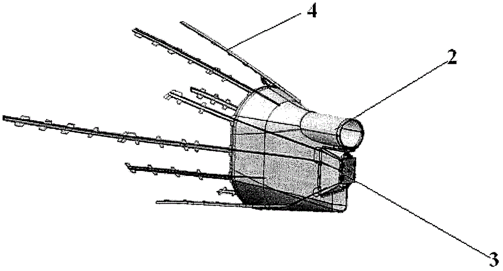
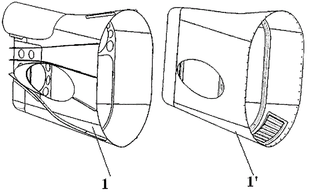
[0021] Such as figure 1 As shown, the aircraft stall recovery device of the present invention includes a housing 1 , an umbrella ejection mechanism, a bearing support 3 and a plurality of long girders 4 . Among them, such as figure 2 As shown, the outer shell 1 has substantially the same shape as the replaced aircraft tail cone 1', and the outer shell 1 can be made of various light metal materials. In an embodiment of the present invention, the outer shell 1 is made of steel material constitute.

[0022] Such as figure 1 As shown, the parachute ejecting mechanism is the ejection barrel 2, and a stall parachute is placed in the ejection barrel 2. In the flight test, the ejection barrel 2 can eject the stall parachute arranged therein. In addition, the ejection barrel 2 also includes a parachute-throwing part, which is connected to the bearing support through explosive bolts. When the parachute needs to be thrown, it is only necessary to activate the explosive bolt, and the...


PUM


Abstract

The invention discloses an airplane stall recovery device, which is capable of replacing an original airplane tail cone in an airplane stall test. The airplane stall recovery device comprises a shell, a parachute outlet mechanism, a load-carrying support and a plurality of long booms, wherein the shell is the same as the replaced airplane tail cone in shape; the parachute outlet mechanism is located above behind the interior of the shell; a stall parachute is put in the parachute outlet mechanism; the load-carrying support is located at the rear side of the interior of the shell and is connected with the parachute outlet mechanism; the load-carrying support is capable of transmitting the load of the parachute outlet mechanism to the shell of the recovery device; the long booms extend from the surface of the inner side of the shell to the joint of a stall device and a fuselage; and the long booms can be connected with the load-carrying structure of the fuselage so as to transmit the load on the shell of the recovery device to the fuselage. According to the airplane stall recovery device disclosed by the invention, the original airplane tail cone is integrally replaced in an airplane stall / tail spin trial flight test, and moreover, an appearance which is the same as the original airplane tail part is basically kept, thus, the pneumatic performance when airplane stall / tail spin trail flight is performed cannot be influenced.

Description

technical field [0001] The invention relates to an aircraft flight test device, in particular to a stall recovery device used in an aircraft stall / spin flight test. Background technique [0002] Stall refers to the flight condition corresponding to when the aircraft reaches the maximum available lift coefficient. The stall state of an aircraft is usually defined by the stall angle of attack or stall speed. At stall angle of attack, there may be uncommanded roll, pitch, or yaw motion of the aircraft due to flow separation, or unacceptable jitter or structural vibrations that limit the maximum available lift coefficient. When the flight angle of attack exceeds the stall angle of attack, although the lift coefficient may continue to increase, severe longitudinal or lateral instability will occur, followed by loss of control of the aircraft. [0003] The flight test of an aircraft is the most important link in the process of aircraft development, and it is the process of testi...

Claims


Application Information

Patent Timeline
Patent Type & Authority Patents(China)
IPC IPC(8): B64D17/80
Inventor 梅鹤生郝新超孟庆功钱敏程凯李希岩于雷张璞
Owner COMAC
Why Eureka
Eureka Blog
Learn More