Fixed structure of disk for setting vortex in vortex type compressor

A technology of scroll compressor and fixed structure, which is applied in the direction of rotary piston/oscillating piston pump components, mechanical equipment, machines/engines, etc., and can solve problems such as compressed gas leakage, compressor noise and vibration, and bolt looseness , to achieve the effect of improving performance and reliability and preventing omissions

Inactive Publication Date: 2005-06-15
LG ELECTRONICS (TIANJIN) APPLIANCES CO LTD
View PDF0 Cites 0 Cited by
  • Summary
  • Abstract
  • Description
  • Claims
  • Application Information

AI Technical Summary

Problems solved by technology

Since the fixing direction of the bolts for installing the fixed scroll (6) is also parallel to the axial direction, therefore, affected by the air pressure in the compression c

Method used


Image

  • Fixed structure of disk for setting vortex in vortex type compressor
  • Fixed structure of disk for setting vortex in vortex type compressor
  • Fixed structure of disk for setting vortex in vortex type compressor

Examples


Example Embodiment

[0029] The present invention will be described in detail below with reference to the drawings and embodiments.

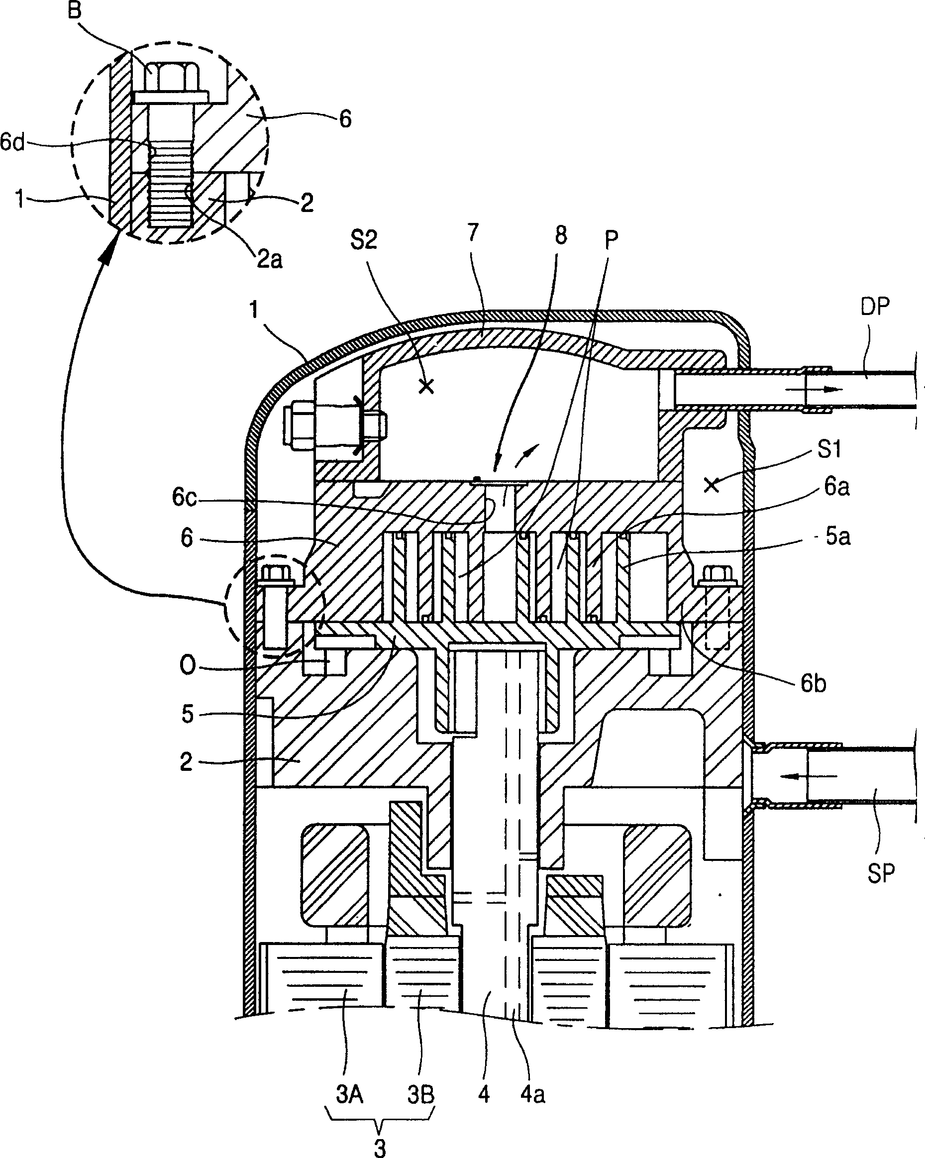
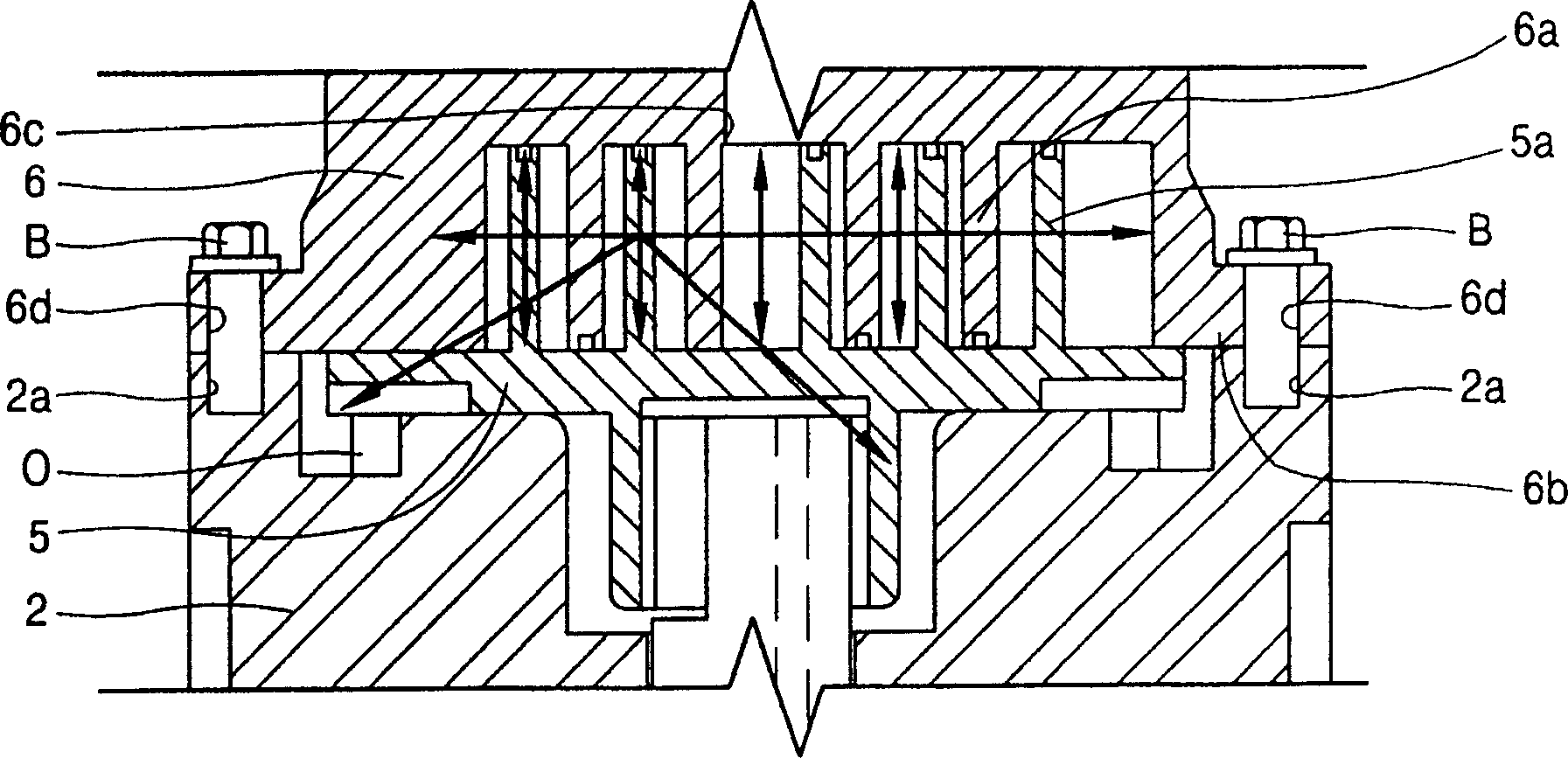
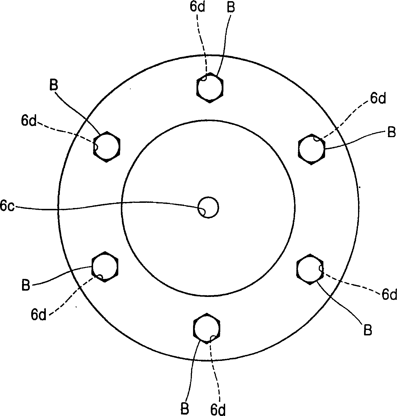
[0030] Figure 4 It is a longitudinal sectional front view structure diagram of the upper bracket and the scroll fixing structure of the present invention, Figure 5 Is a schematic diagram of the pressure in the compression chamber of the present invention, Figure 6 Yes Figure 5 "I-I" section view, Figure 7 It is a top structural view of the fixed scroll of the present invention in a fixed state.

[0031] As shown in the figure, the existing scroll compressor consists of a housing (11) equipped with an intake pipe (SP) and an exhaust pipe (DP), and upper brackets (12) are fixed on the upper and lower sides of the inner circumferential surface of the housing (11). ) And the lower bracket (not shown), the drive motor (13) installed between the upper bracket (12) and the lower bracket, inserted into the center of the drive motor (13), and the transmission drive motor (1...


PUM


Abstract

The invention discloses a fixed scroll disk fixing structure of scroll compressor. Said scroll compressor includes upper support frame mounted in the interior of external shell, fixing scroll disk fixed on the upper support frame and movable scroll disk which can be meshed with fixed scroll disk and can be used for forming several comperssion chambers. In the scroll disk mounting structure of scroll compressor at least one fixed scroll disk whose screw holt is inclined to oxial direction. Said scroll disk mounting structure can prevent leakage of compressed air and vibration due to noise so as to raise the performance and reliability of compressor.

Description

technical field [0001] The present invention relates to the structure of a scroll compressor, more specifically to a fixed scroll fixing structure of a scroll compressor that can improve the fixing strength in the axial, radial and tangential directions when fixing the upper bracket and the fixed scroll. Background technique [0002] Generally speaking, the scroll compressor is one of the compressors with high efficiency, low noise and widely used in various fields. It can form multiple compression chambers through the relative rotational movement of the fixed scroll and the movable scroll. When the compression chamber gradually moves to the central position, the volume of the compression chamber also gradually decreases, so that the continuous process of suction→compress gas→exhaust can be repeated. [0003] figure 1 It is the longitudinal section front view structural diagram of the existing scroll compressor, figure 2 It is a schematic diagram of the pressure force in...

Claims


Application Information

Patent Timeline
IPC IPC(8): F04C29/00
Inventor 金正勋
Owner LG ELECTRONICS (TIANJIN) APPLIANCES CO LTD
Why Eureka
Try Eureka