
Rope brake for overspeed upgoing elevator

A rope clamp and elevator technology, which is applied in elevators, transportation and packaging, etc., can solve the problems of prolonged stopping time of axle boxes, large elevator running inertia, and small size, and achieves light weight, compact structure, and easy reset Effect

Active Publication Date: 2005-06-29
宁波申菱机电科技股份有限公司
View PDF2 Cites 18 Cited by
  • Summary
  • Abstract
  • Description
  • Claims
  • Application Information

AI Technical Summary

Problems solved by technology

[0002] At present, the mechanism to prevent the elevator from overspeeding upwards adopts the method of triggering the limiter switch due to overspeed, so that the elevator trailing machine stops running, and then clamps the guide rail with the safety gear to stop the axle box; these methods are due to the large inertia of the elevator. The braking and stopping time of the axle box is prolonged, and there are hidden dangers of unsafety; in order to implement overspeed protection and smooth braking, a Chinese utility model patent discloses an "elevator traction rope brake", the patent number: 01274866.8, and the technical solution of this patent is similar to A kind of "elevator car brake device with spring-driven brake block" disclosed in the invention patent of our country: CN1084482A, is made of a custom-made brake lining plate fixed on the vertical plate, which is parallel to the custom-made brake lining plate. The brake lining, the pin shaft guiding the dynamic brake lining up and down, and the connecting arms on both sides of the two brake linings form a clamping mechanism. The movable liner is hinged, and the other end is hinged with the sliding shaft that slides through the oblong hole of the vertical plate. The sliding shaft is tied by the energy storage spring fixed at the bottom, connected with the trigger mechanism, and reset by the reset mechanism; it has simple structure and low cost. , small size and other characteristics; the disadvantage is that the trigger force required to pull the lock hook is relatively large, and the clamping rope depends entirely on the spring force of the energy storage spring, and the rope is clamped by the positive pressure of the parallel splint, and the clamping force required is also large.

Method used


Image

  • Rope brake for overspeed upgoing elevator
  • Rope brake for overspeed upgoing elevator
  • Rope brake for overspeed upgoing elevator

Examples


Embodiment Construction

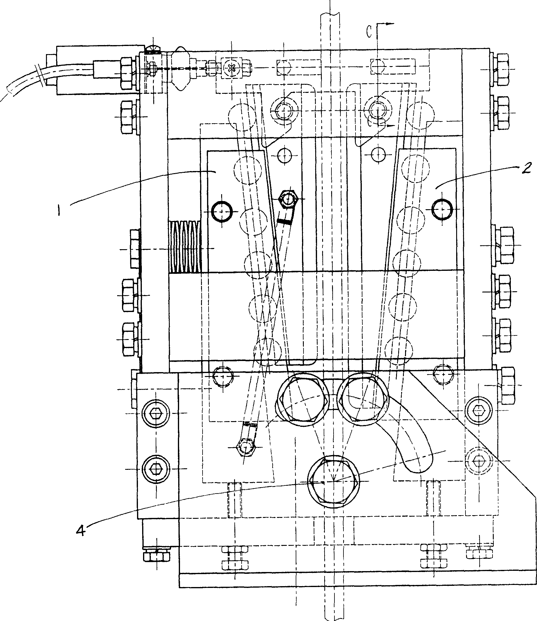
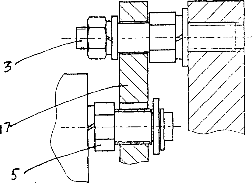
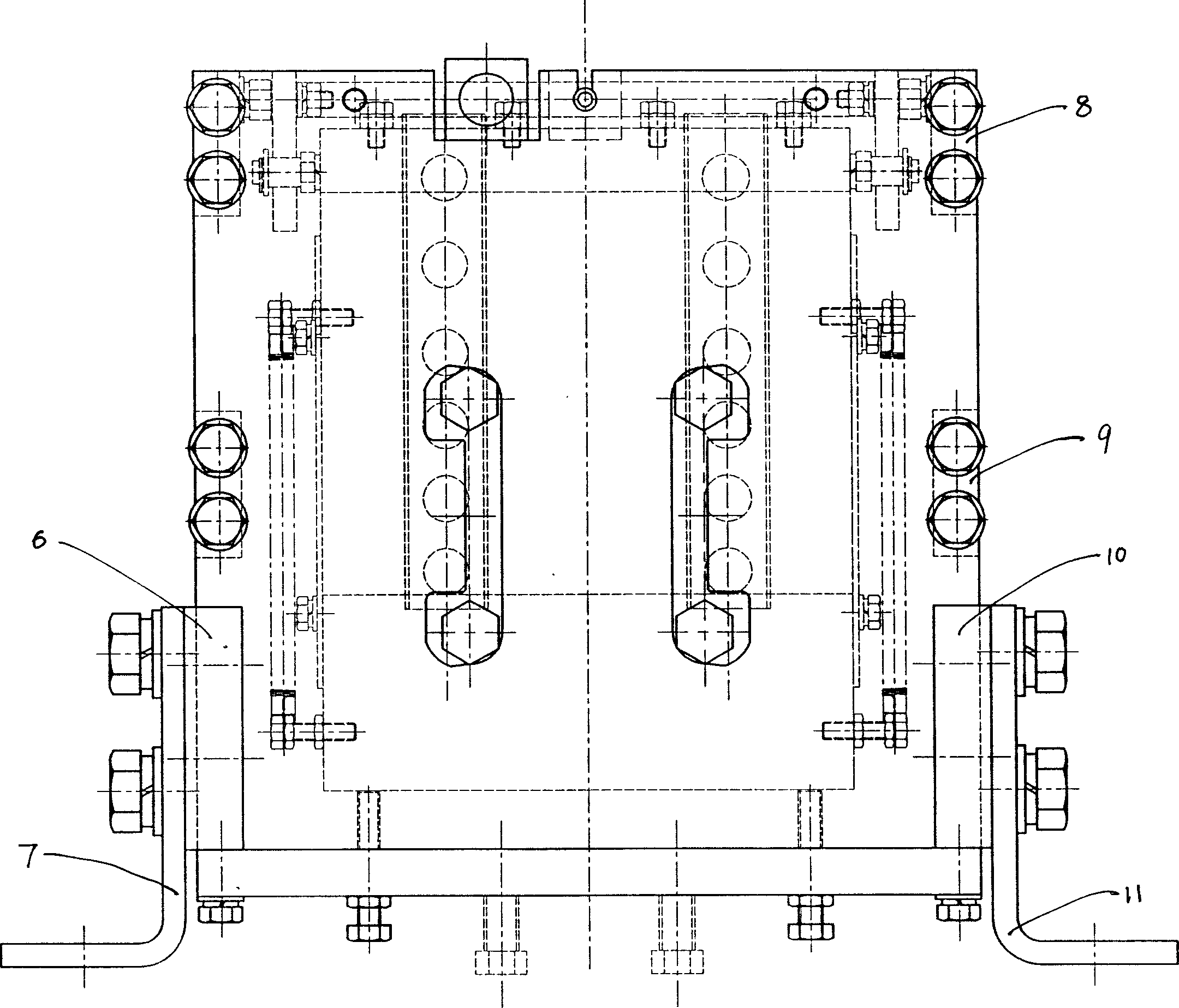
[0015] Depend on Figure 1-Figure 6 As shown, a kind of elevator upward speeding rope clamp 38 of the present invention is installed between the elevator traction wheel 37 and the guide wheel 39, and the other end of the elevator traction wheel 37 is the car 36; Above the counterweight 40 below, steel rope 35 passes in the middle of the upward overspeed rope gripper 38 of the elevator, and is positioned by positioning bolt 4; Rack base plate 26 and the frame main board 34 and the rack back plate 20 fixed on the rack base plate, and the upper, middle and lower rack side plates 8 fixed on the left and right sides between the rack main board and the rack back plate , 9, 10, and 6; a wedge-type wire rope clamping mechanism and a trigger mechanism are installed in the frame, and said clamping mechanism has movable wedges 33, 21, fixed wedges symmetrically arranged on the front and rear sides of the steel rope 35 Blocks 27, 24, liner plates 31, 22 are fixed on the movable wedge, an...


PUM


Abstract

The invention is an elevator up-going clamping rope device installed between the tract wheel and guide wheel or right under the guide wheel. The steel wire crosses the device from the center. It is for the amendment of failures and safety assurance, includes steel wire clamping mechanism and trigger mechanism. The clamping mechanism has a fixed wedge and an active wedge symmetrically arranged in front and back side of the steel wire. The trigger mechanism consists of transient trigger, clasp board and the trigger pole fixed between and with the two clasp boards; the clasp board links with the active wedge hanging by active key, the trigger wire is fixed to the trigger pole, links to the elevator speed governor, is manually resettable by lift upwards slightly the pole after inserted into the hole previously made in the active wedge. The invention is of light trigger force, short trigger trip, adjustable brake force, many features such as tight structure, small size, light weight, easy to reset and so on. The clamp will become tighter and tighter when the elevator travels on inertia.

Description

technical field [0001] The invention relates to the technical field of fault correction or safety devices for elevator operation, in particular to a brake device that acts on the guide ropes of a car with friction. Background technique [0002] At present, the mechanism to prevent the elevator from overspeeding upwards adopts the method of triggering the limiter switch due to overspeed, so that the elevator trailing machine stops running, and then clamps the guide rail with the safety gear to stop the axle box; these methods are due to the large inertia of the elevator. The braking and stopping time of the axle box is prolonged, and there are hidden dangers of unsafety; in order to implement overspeed protection and smooth braking, a Chinese utility model patent discloses an "elevator traction rope brake", the patent number: 01274866.8, and the technical solution of this patent is similar to A kind of "elevator car brake device with spring-driven brake block" disclosed in th...

Claims


Application Information

Patent Timeline
IPC IPC(8): B66B5/24
Inventor 李建忠童安全
Owner 宁波申菱机电科技股份有限公司
Learn More