
Residual current protection trip mechanism and release

A technology of residual current and tripping mechanism, applied in the direction of protection switch operation/release mechanism, protection switch, emergency protection device, etc., can solve the problems of small design margin, false tripping, large tripping force, etc., and improve work The effect of reliability and accurate positioning

Active Publication Date: 2014-10-15
SCHNEIDER ELECTRIC IND SAS
View PDF4 Cites 0 Cited by
  • Summary
  • Abstract
  • Description
  • Claims
  • Application Information

AI Technical Summary

Problems solved by technology

[0006] In the circuit breaker of the prior art, although the cooperation between the residual current protection device and the thermal magnetic release mechanism can be realized, the tripping force provided by the residual current protection device is required to be large, and the design margin is small. Short-circuit faults, polluted mechanisms, etc., cause the release to fail to trip or trip by mistake, reducing reliability

Method used


Image

  • Residual current protection trip mechanism and release
  • Residual current protection trip mechanism and release
  • Residual current protection trip mechanism and release

Examples


Embodiment Construction

[0036] In describing the embodiments shown in the figures, specific terminology is employed for the sake of clarity. However, the disclosure of this patent specification is not intended to be limited to the specific terms so selected, and it is to be understood that each specific element includes all technical equivalents which operate in a similar manner and achieve a similar effect. In the following description, "comprising", "comprising" and other similar terms should be understood as open-ended, and it is intended that there may be other unspecified elements or components in addition to the specified ones, and These unspecified elements or components can be easily conceived by those skilled in the art according to the teaching of the present invention.

[0037] Although the exemplary embodiments are described with some technical limitations with reference to the drawings, these descriptions are not intended to limit the scope of the present invention, and not all parts or ...


PUM


Abstract

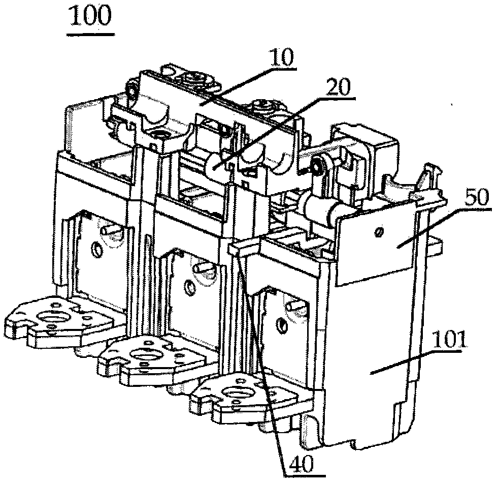
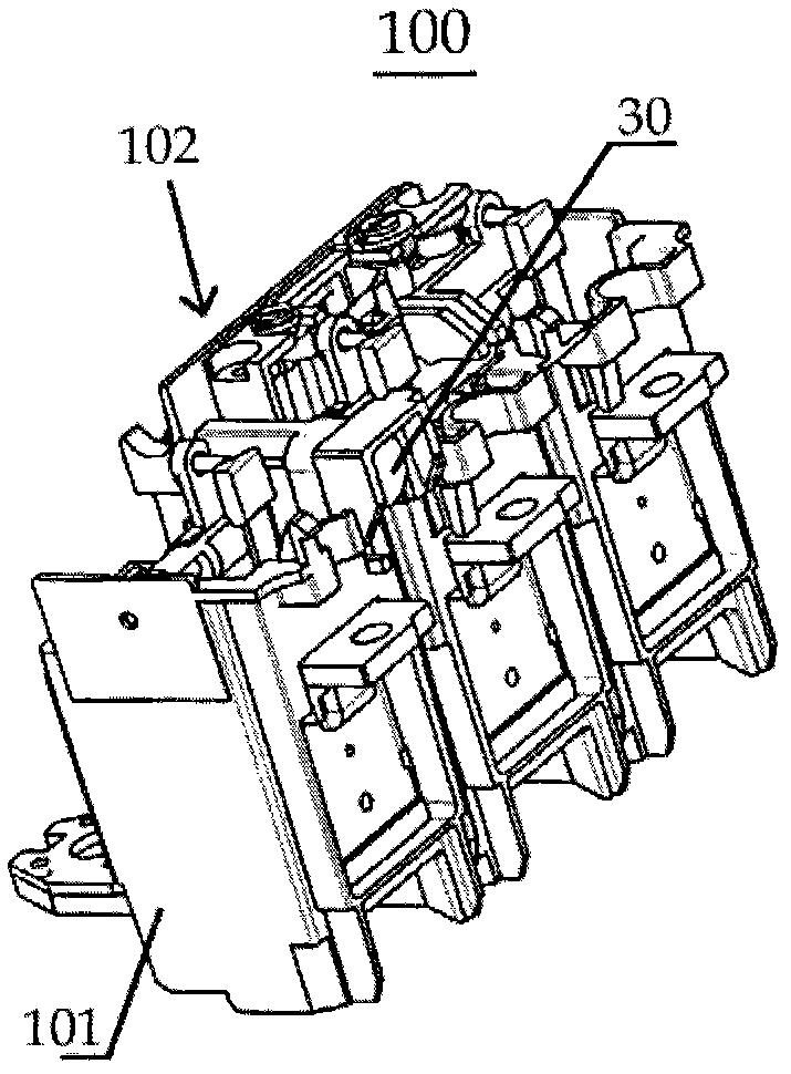
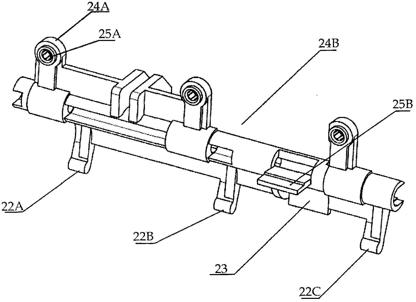
The invention discloses a residual current protection tripping mechanism and a tripper. The tripping mechanism includes a drawbar and a jumper. The jumper interacts with the drawbar so that the jumper operates normally. The drawbar has a first engaging part and a second engaging part, and the first engaging part interacts with the residual current protection rod of the residual current protection device, causing the drawbar to move, and then the drawbar moves between the position and the unlocking position. The tripping buckle is actuated, and the second engaging portion interacts with at least one protection device of an overload protection device and a short circuit protection device, causing the drawbar to move, thereby activating the tripping buckle tripping. The residual current protection device, overload protection device, short-circuit protection device, etc. share a trip protection mechanism, thus simplifying the structure and saving costs.

Description

technical field [0001] The present invention relates to a molded case circuit breaker, and in particular to a thermal electromagnetic release for the molded case circuit breaker. The thermal electromagnetic release can cooperate with a residual current protector to realize overload protection and short circuit protection at the same time , Also realize residual current protection. Background technique [0002] Molded case circuit breakers are widely used in medium and low voltage circuits to distribute electric energy and protect circuits, power supplies and electrical equipment. [0003] Molded case circuit breakers are usually assembled with a release, which performs protection functions, namely: overload protection, short circuit protection, time delay protection and leakage protection. As a traditional mechanical structure, circuit breakers generally provide thermal overload protection and short circuit protection. The thermal overload protection device is usually impl...

Claims


Application Information

Patent Timeline
Patent Type & Authority Patents(China)
IPC IPC(8): H01H71/12H01H83/14
CPCH01H83/22H01H71/1009H01H2009/0088H01H71/505H01H71/10
Inventor 孙海涛施俊昌胡继伟范文杰
Owner SCHNEIDER ELECTRIC IND SAS
Learn More