

Pipe-line type water turbine generator
A generator set, pipeline technology, applied in the direction of electric components, engine components, machines/engines, etc., can solve the problems of uneconomical economy, large investment, insufficient utilization of water energy, etc.
Inactive Publication Date: 2005-06-29
陈文斌
View PDF0 Cites 5 Cited by
- Summary
- Abstract
- Description
- Claims
- Application Information
AI Technical Summary
Problems solved by technology
Such a generating set can only utilize the first-level drop of water, and is not suitable for setting up multi-stage generating sets in the same dam area, otherwise the investment is too large, economically uneconomical, and the existing generators do not fully utilize water energy
Method used
View moreImage
Smart ImageViewing Examples

Examples
Embodiment Construction
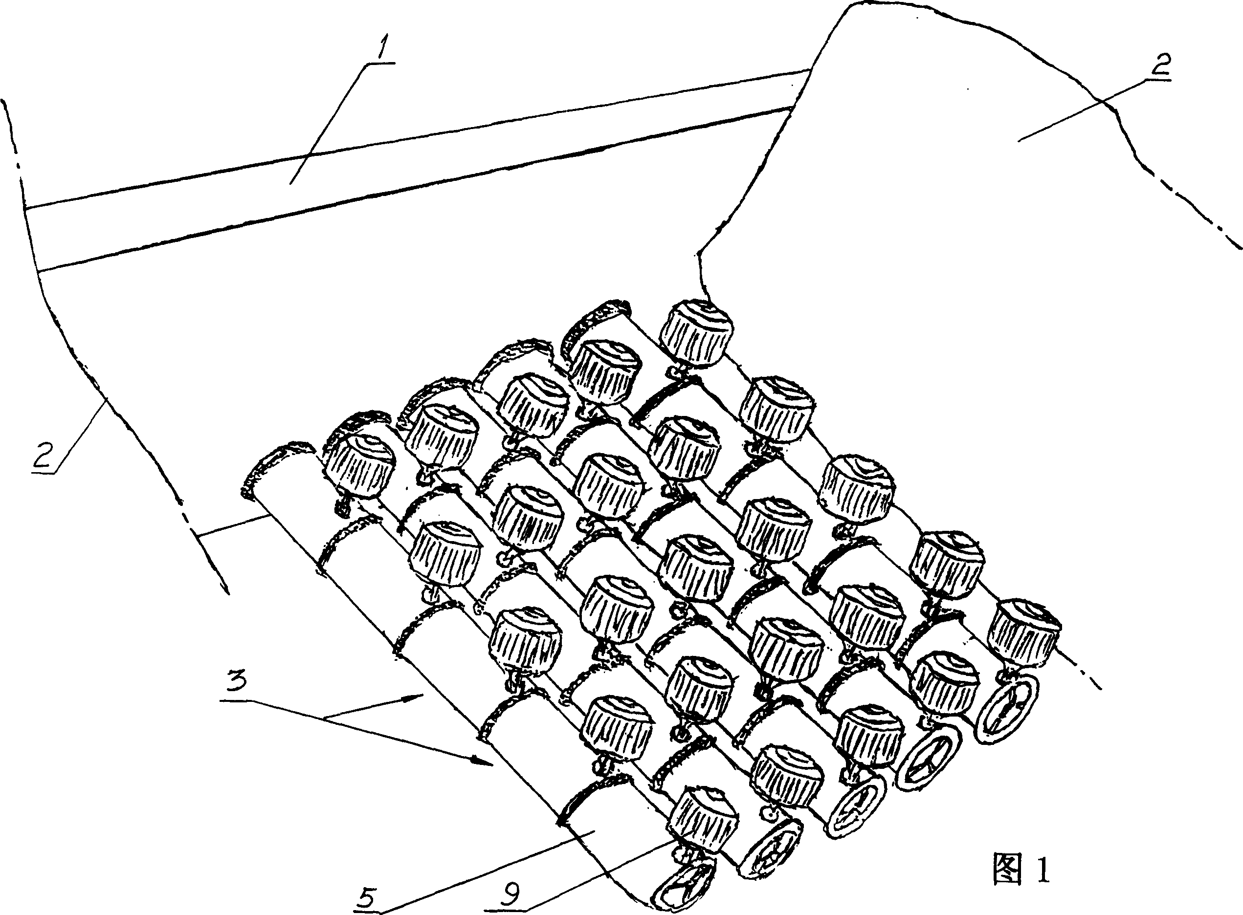
[0017] Referring to Figures 1 to 3, the unit is equipped with five series pipelines as shown in Figure 1, each of which is composed of five power generation unit pipelines 3 connected, each section of pipeline body 5 is 5 meters in length, 1.6 meters in inner diameter, and 0.2 meters in thickness, each The generating capacity of generator 9 is 0.5-10KW.
Login to View More PUM
 Abstract
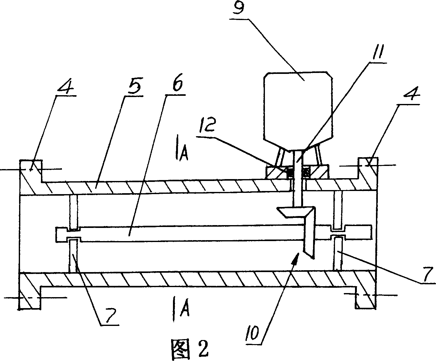
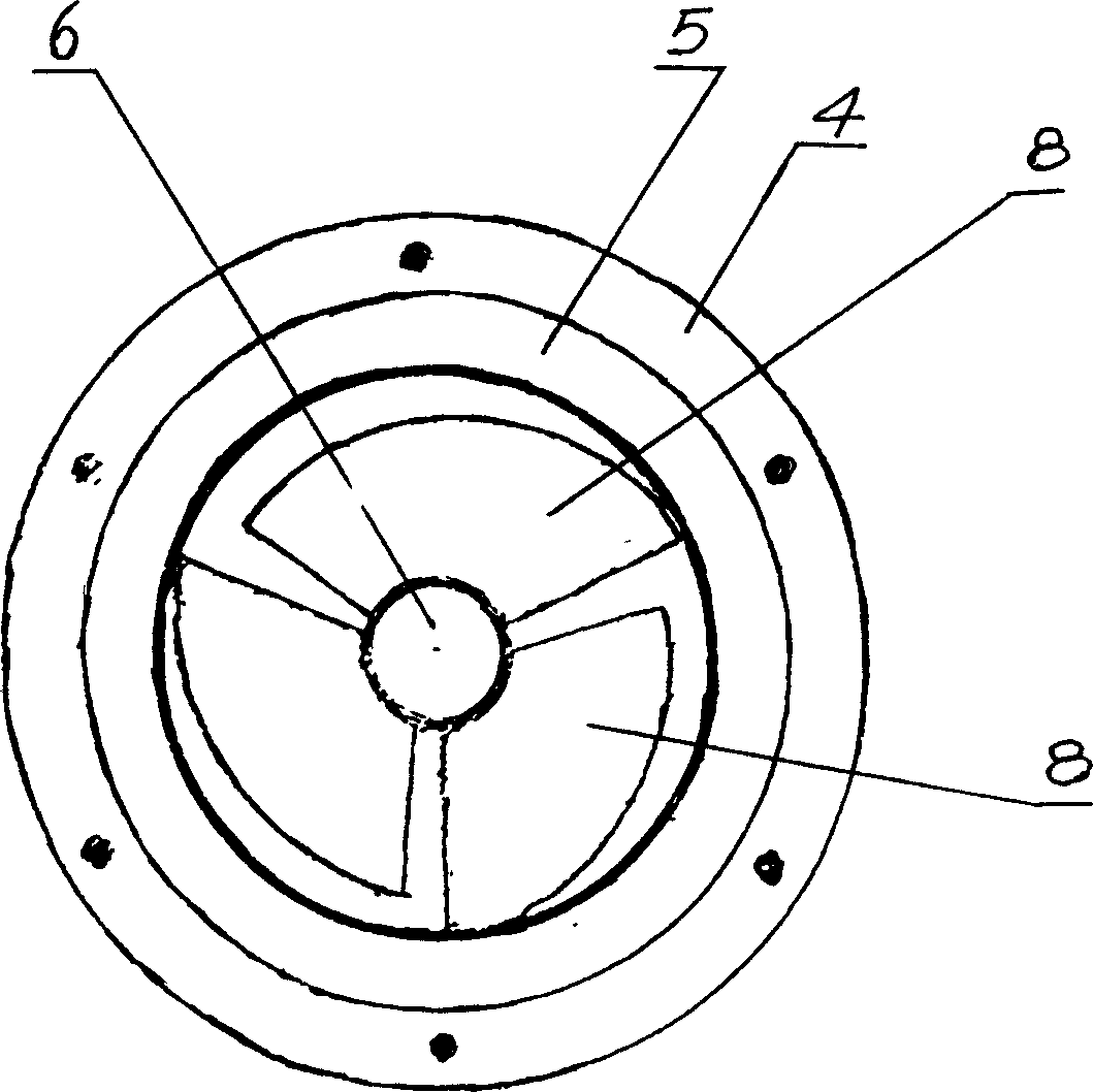
A pipe-type hydroelectric generator set, which is composed of a plurality of power generation unit pipes 3, each of the power generation unit pipes 3 has pipe bodies 5 connected to flanges 4 at both ends, and the pipe body 5 is arranged according to the axial direction of the pipes. An impeller shaft 6 is provided, and the two ends of the impeller shaft 6 are respectively installed in the pipeline through a bracket 7, and three blades 8 are evenly arranged on the circumference of the impeller shaft 6, and one end of the impeller shaft 6 is passed through a reversing transmission pair 10 It is connected with the rotor shaft 11 of the generator 9 installed on the pipe body 5 , and there is a seal 12 between the generator rotor shaft 11 and the shaft hole of the pipe body 5 . The device is suitable for being installed under river dams, streams in mountainous areas, under gully dams, etc., and can make full use of hydropower resources to generate electricity.
Description
technical field [0001] The invention relates to a pipeline type hydraulic generator set under a barrage. Background technique [0002] In the prior art, most of the hydroelectric power generation is to install a generator set on one side of the dam, and use the drop of water to do work. Such generating sets can only utilize the first-level drop of water, and are not suitable for setting multi-stage generating sets in the same dam area, otherwise the investment is too large, economically uneconomical, and the existing generators are insufficient for the utilization of water energy. On the other hand, there are many rivers and streams in the vast mountainous areas of southern my country, and the water surface drop is relatively large, which is conducive to the installation of multi-stage generator sets in the same dam area. Contents of the invention [0003] The technical problem to be solved by the present invention is to propose a pipe-type hydroelectric generator set, wh...
Claims
Login to View More Application Information
Patent Timeline
 IPC IPC(8): F03B13/00H02K7/00H02K7/14
Inventor陈文斌
Owner陈文斌