Method and system for heat supply network water supplementing treatment

A treatment system and water replenishment technology, applied in the field of industrial water treatment, can solve the problems of the body and supporting equipment occupying a large area, high operating costs, and large land occupation, achieving low inlet water quality requirements, high degree of automation, and reduced floor space. Effect

Pending Publication Date: 2020-02-11
河北涿州京源热电有限责任公司 +1
View PDF4 Cites 3 Cited by
  • Summary
  • Abstract
  • Description
  • Claims
  • Application Information

AI Technical Summary

Problems solved by technology

The disadvantages of this treatment method are: ① The discarded ion exchange resin is a dangerous chemical, which is not easy to dispose of.
②A supporting ion exchanger resin regeneration system is required, which occupies a large area
③ It is necessary to discharge a large amount of regeneration waste liquid, which contains high salt content, which is not conducive to environmental protection
④ It is necessary to add a large amount of chlorine-reducing agents to prevent corrosion of heat exchangers, increase operating costs, and pollute the environment by drainage
This treatment method has the following disadvantages: ①The process flow is long, and the body and supporting equipment occupy a large area; ②There are many equipments, and the investment is large; ③The operating cost is high, which is not conducive to energy saving; ④The water utilization rate is not higher than 65%, and the waste water is discharged more. Not conducive to environmental protection; ⑤Use of dangerous chemicals hydrochloric acid, sodium hydroxide and sodium hypochlorite, high management costs

Method used


Image

  • Method and system for heat supply network water supplementing treatment

Examples


Embodiment Construction

[0014] The present invention will be described in detail below in conjunction with the accompanying drawings. The protection scope of the present invention is not limited to the embodiments, and any changes made by those skilled in the art within the scope defined in the claims also belong to the protection scope of the present invention.

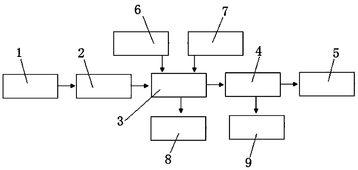
[0015] The present invention is used for the treatment system of heating net replenishment treatment method, as figure 1 As shown, it includes tap water supply pipeline, No. 1 water tank 1, filter 3, electric adsorption device 4, No. 2 water tank 5, air compressor 6, backwash pump 7, No. 1 underground pool 8, and No. 2 underground pool 9. The electric adsorption device 4 is provided with a water outlet and a flushing drain, and the filter 3 is provided with an air inlet, a backwashing water inlet and a flushing drain. The tap water supply pipeline is connected to the No. 1 water tank 1, the No. 1 water tank is connected to the filter 3 thr...


PUM

PropertyMeasurementUnit
hardnessaaaaaaaaaa
hardnessaaaaaaaaaa
turbidityaaaaaaaaaa

Abstract

The invention relates to a method and a system for heat supply network water supplementing treatment. The method comprises the steps: reclaimed water for heat supply network water supplementation goesthrough a filter to remove suspended matters and organic matters, and calcium, magnesium and chloride ions are removed through an electric adsorption device to make treated supplemented water meet the requirements of heat supply network water supplementation. The system comprises a tap water supply pipeline, a first water tank, the filter, the electric adsorption device, a second water tank, an air compressor, a backwashing pump, a first underground water pool and a second underground water pool. The tap water supply pipeline is connected with the first water tank, the first water tank is connected to the filter through a water pump, the filter is connected to the second water tank through the electric adsorption device, and the second water tank is connected with a heat supply network. The air compressor and the backwashing pump are connected with the filter. Filtering and adsorbing treatments of the water for the heat supply network make the water meet the required water supplementing quality standard of the heat supply network, and the method and the system have the advantages of short process flow, small occupied area, high water utilization rate, low wastewater discharge andfacilitation of environmental protection.

Description

technical field [0001] The invention belongs to the technical field of industrial water treatment, and relates to a method and system for water replenishment treatment of a heating network. Background technique [0002] The development of regional centralized heating can save energy, protect the environment, improve heating efficiency, and ensure people's lives. In order to prevent the thermal system, especially the heat exchanger from corrosion and fouling, the water supply of the heating network needs to meet certain requirements. CJJ34-2010 "Code for Design of Urban Heating Pipeline Network" requires that the water hardness of the heating network should be ≤0.6mmol / L. The heat exchanger is often made of stainless steel (304, 316 or 316L, etc.). In order to prevent stress corrosion of the heat exchanger, chloride ions are required to be ≤ 25mmol / L. [0003] Thermal companies generally adopt traditional treatment methods, that is, use sodium ion exchangers to remove calci...

Claims


Application Information

Patent Timeline
Patent Type & Authority Applications(China)
IPC IPC(8): C02F9/06C02F103/02
CPCC02F1/4691C02F1/001C02F2103/02C02F2303/14
Inventor 刘政修李刚韩志勇王斌杨勇梅东升毛永清郭永红于海琴李朝晖何晓迪白玉莲郭强段立国
Owner 河北涿州京源热电有限责任公司
Why Eureka
Try Eureka