Method for slowering frosting speed of heat exchanger outside air-source heat pump chamber and heat pump
An air source heat pump, outdoor side technology, applied in lighting and heating equipment, damage protection, refrigeration components, etc., can solve problems such as energy consumption
- Summary
- Abstract
- Description
- Claims
- Application Information
AI Technical Summary
Problems solved by technology
Method used
Image

Examples
Embodiment 1
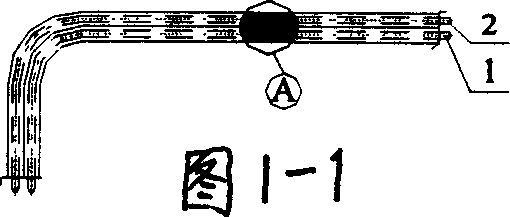
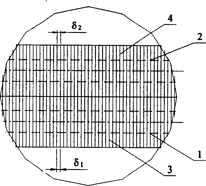
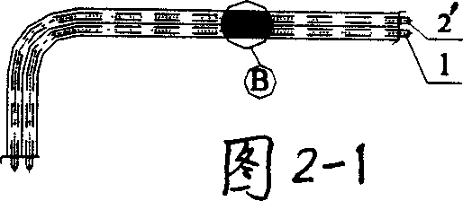
[0026] Embodiment 1. An air source heat pump, comprising an outdoor heat exchanger (first row of heat transfer tubes) 1 and a cooling and drying device (second row of heat transfer tubes) 2' connected in series to the refrigerant circulation pipeline. Spacing δ of fins 3 on the first row of heat transfer tubes 1 1 Same as the original heat exchanger, the distance between the fins 4' on the second row of heat transfer tubes 2' is compared with the original heat exchanger by δ 2 increased to δ 3 . In use, the low-temperature refrigerant liquid first passes through the heat transfer tube 2', and exchanges heat and moisture with the air through the heat transfer tube 2' and the fins 4' on it to reduce the humidity of the air; the dried air then enters the heat transfer tube The tube 1 and the fins 3 above it perform heat and moisture exchange. Through this arrangement, most of the moisture in the air frosts on the heat transfer tube 2' and the fins 4' above it; the frost on the...
Embodiment 2
[0027] Embodiment 2. An air source heat pump. A cooling and drying coil 8 connected in series is added to the air inlet side of the existing outdoor heat exchanger. The diameter D of the cooling and drying coil 8 is smaller than that of the first row of heat transfer tubes 1 and the second row. The diameter d of the second row of heat transfer tubes 2. During the heating operation of the heat pump, the liquid supercooled refrigerant first passes through the cooling and drying coil 8, where the air is dried, and most of the moisture in the air frosts here; the heat transfer tube 1 and the fins 3 on it And the amount of frosting on the heat transfer tube 2 and the fins 4 above it is greatly reduced. In this way, the number of defrosts of the heat pump can be reduced. During defrosting, the high-temperature refrigerant gas first passes through the cooling coil 8, and then enters the heat transfer tubes 1 and 2. In this way, the frost layer is easily removed and the defrosting t...
Embodiment 3
[0028] Embodiment 3 In this embodiment, heat transfer steel wires 9 are welded on the outer wall of the cooling and drying coil 8 , and the steel wires 9 on both sides of the coil 8 are arranged in a staggered arrangement. By adding heat transfer steel wires, the cooling and drying effect of the air can be increased, and the frosting speed on the heat transfer tube 1 and the fins 3 on it and the heat transfer tube 2 and the fins 4 on it can be slowed down. Others are the same as embodiment 2.
PUM
 Abstract
Description
Claims
Application Information
 - R&D
- Intellectual Property
- Life Sciences
- Materials
- Tech Scout
- Unparalleled Data Quality
- Higher Quality Content
- 60% Fewer Hallucinations
Browse by: Latest US Patents, China's latest patents, Technical Efficacy Thesaurus, Application Domain, Technology Topic, Popular Technical Reports.
© 2025 PatSnap. All rights reserved.Legal|Privacy policy|Modern Slavery Act Transparency Statement|Sitemap|About US| Contact US: help@patsnap.com